
PWM controller with PIC18f2455

The described circuit utilizes the capabilities of the PIC18F2455 microcontroller to implement pulse width modulation (PWM) for controlling the brightness of an LED. The circuit is designed to demonstrate the operation of the CCP (Capture/Compare/PWM) module, which is integral to the microcontroller's functionality. The PWM signal is generated with the aid of Timer 2, which is configured to work in sync with the CCP module.
In this setup, the LED's brightness is controlled through a NPN transistor, specifically the BC547, which acts as a switch for the LED connected to a 2x16 LCD display. The PWM output from the CCP1 pin is directly responsible for modulating the transistor's base current, thereby controlling the LED's brightness based on the duty cycle of the PWM signal.
The duty cycle is determined by the values obtained from an analog-to-digital converter (ADC) connected to a potentiometer. This configuration allows for a variable resistance, translating into a voltage level that the ADC reads. The relationship between the ADC reading and the PWM duty cycle is critical, as it allows for a range of brightness levels from fully off (0V) to fully on (5V).
The period of the PWM signal is calculated using the formula provided, where PR2 is employed to define the duration of the PWM cycle. The maximum duty cycle is also calculated, ensuring that the PWM signal can utilize the full 10-bit resolution available from the ADC. This high resolution allows for finer control over the brightness levels, making the circuit suitable for applications requiring precise LED dimming.
In summary, this circuit exemplifies the application of PWM in microcontroller-based systems, showcasing how digital control can effectively manage analog components like LEDs. The integration of ADC for input and the use of the CCP module for output demonstrates a practical approach to modern electronic design.The use of pulse width modulation (PWM) is common for the use of controlling power to a particular electrical device. Motor speed control, LED contrast control, power supplies are some of the example usage of PWM. 18 series PIC always come with a CCP module which is capable of generating PWM. The picture below shows an example of using the capture/compare/pwm (CCP) module to control the LED brightness.
PWM duty cycle is set accordingly using the value obtain from the potential meter through the ADC with 5v being the brightness and 0v dimmest for the LED. The test circuit below is constructed to test the PWM module of PIC18f2455. LED of the 2x16 LCD is controlled by a NPN transistor BC547. PWM output is feed through CCP1 for the brightness control. The example below uses the code from ADC and LCD guides. Next step would be to set the CCP module to function as a PWM. Timer 2 is tied to the PWM function for the generation of CCP. PR2 is used to determine the Period of the PWM pulse. CCPR1L and bit 4 and 5 of CCP1CON control the duty cycle of the generated PWM. With this we can obtain a pwm period and maximum duty cycle of PWM Period = (255 + 1) * 4 * (1 / (8 * (10^6))) = 0.000128 Max PWM Duty Cycle period = (1024 * (1/(8*10^6))) =0.000128 allowing us to use full 10 bit to control the duty cycle of the PWM. The 10 bit adc value is set in to the corresponding bit for the control of the PWM. Below is the code for the update of pwm duty cycle. Fill attached contain the project for the example. 🔗 External reference
Related Circuits
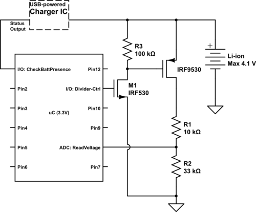
Currently using the PIC24FJ128GA010, there is a plan to utilize an Input/Output port to connect a 4.2 V LiPo battery and monitor the voltage to ensure it does not drop below 3.7 V. It is advised to avoid digital...
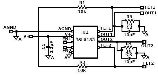
The ISL6185 USB power controller family can be utilized to design a straightforward USB power supply electronic project that offers fully independent overcurrent (OC) fault protection for two or more USB ports. This product family includes sixteen distinct functional...
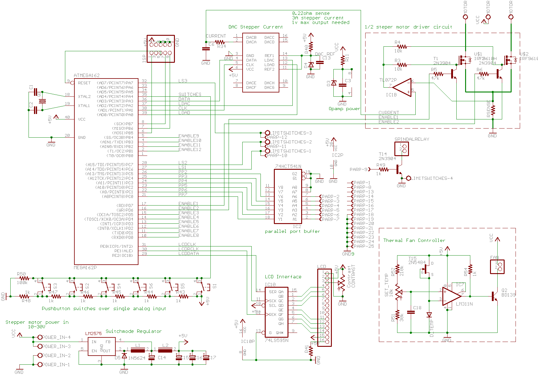
A basic CNC machine was built for a university project, and the completed machine will undergo upgrades over the coming months. The plan includes replacing the small 48-step stepper motors with larger 200-step motors to enhance performance. The project involves...
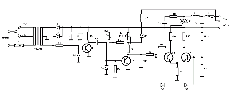
The AC Motor Speed Controller is designed to regulate the speed of AC motors with carbon brushes, applicable to devices such as drills, saws, and vacuum cleaners. The AC Motor Speed Controller operates by adjusting the voltage and current supplied...
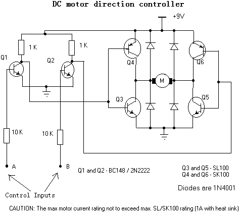
This circuit can control a small DC motor, like the one in a tape recorder. When both the points A & B are "HIGH" Q1 and Q2 are in saturation. Hence the bases of Q3 to Q6 are grounded....

This circuit can control a small DC motor, like the one in a tape recorder. When both the points A and B are "HIGH," Q1 and Q2 are in saturation. Hence, the bases of Q3 to Q6 are grounded....