
Discrete component motor direction controller
This circuit utilizes a transistor-based configuration to control the operation of a small DC motor. The circuit logic is based on the states of two input control signals, A and B. The transistors Q1 and Q2 act as switches that determine the overall state of the motor based on the input signals.
1. **Motor Control States**:
- **Both A and B HIGH**: In this state, transistors Q1 and Q2 are fully saturated, which means they are conducting. This saturation grounds the bases of transistors Q3, Q4, Q5, and Q6. As a result, Q3 and Q5 remain OFF, while Q4 and Q6 turn ON. Since both terminals of the motor receive the same voltage, the motor remains OFF.
- **Both A and B LOW**: The same condition applies here, where Q1 and Q2 are not conducting, leading to the same grounding effect on Q3-Q6. Consequently, the motor remains OFF.
2. **Motor ON Conditions**:
- **A HIGH, B LOW**: In this scenario, Q1 saturates, allowing current to flow through it, while Q2 remains OFF. The bases of Q3 and Q4 are grounded, leading to Q3 being OFF. However, Q4 and Q5 receive HIGH signals, which allows them to conduct. This creates a potential difference across the motor terminals, making the right terminal more positive than the left, thus turning the motor ON.
- **A LOW, B HIGH**: This condition is not described in the input but would typically reverse the roles of A and B, allowing for the motor to potentially operate in the opposite direction, depending on the configuration of the transistors.
3. **Transistor Configuration**:
- The transistors are likely configured in a push-pull arrangement, where Q1 and Q2 control the direction of current flow through the motor, while Q3 to Q6 manage the switching states. This configuration is efficient for controlling motor direction and speed based on logic levels.
4. **Power Supply and Ratings**:
- The circuit should be designed to accommodate the voltage and current ratings of the DC motor, ensuring that the transistors can handle the load without overheating. Appropriate resistors may be necessary to limit base current to the transistors and protect them from damage.
Overall, this circuit provides a simple yet effective means of controlling a small DC motor using basic transistor switches, enabling straightforward control logic through the input signals A and B.This circuit can control a small DC motor, like the one in a tape recorder. When both the points A & B are "HIGH" Q1 and Q2 are in saturation. Hence the bases of Q3 to Q6 are grounded. Hence Q3,Q5 are OFF and Q4,Q6 are ON . The voltages at both the motor terminals is the same and hence the motor is OFF. Similarly when both A and B are "LOW" the motor is OFF. When A is HIGH and B is LOW, Q1 saturates ,Q2 is OFF. The bases of Q3 and Q4 are grounded and that of Q4 and Q5 are HIGH. Hence Q4 and Q5 conduct making the right terminal of the motor more positive than the left and the motor is ON. When A is LOW and B i 🔗 External reference
Related Circuits
The schematic below illustrates 4 methods of controlling a relay with a digital logic signal. Figure (A) can probably be used in most cases where the relay coil requires 100 mA or less and the input current is 2...
The project involves displaying the current room temperature using an LM35 temperature sensor. This schematic differs from a previous schematic that utilized a multiplexed seven-segment display. In the earlier schematic, the display select I/O pins were RA0, RA1, RA2,...
The circuit described here is for a general purpose device that can control DC devices which draw up to a few amps of current. The circuit may be used in either 12 or 24 Volt systems with only a...

The main requirements are a directional antenna, such as a ferrite rod or frame, and a screened case for the equipment. In the past, some competitors modified standard medium wave receivers to operate on the 160m band by retuning...
This simple DC motor control or PWM circuit using a 555 IC can be utilized to regulate the speed of a DC motor. The circuit is straightforward and can be assembled quickly if all components are readily available. The described...
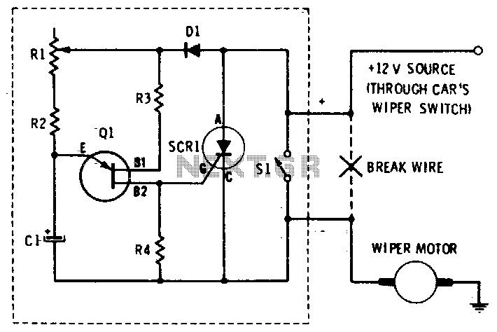
This circuit provides complete speed control over a car's windshield wipers. The wipers can be slowed down to any rate, even down to four sweeps per minute. The controller consists of two principal circuits: the rate-determining circuit, which is...
Warning: include(partials/cookie-banner.php): Failed to open stream: Permission denied in /var/www/html/nextgr/view-circuit.php on line 713
Warning: include(): Failed opening 'partials/cookie-banner.php' for inclusion (include_path='.:/usr/share/php') in /var/www/html/nextgr/view-circuit.php on line 713