
PWM fan controller with PIC 12F675
The circuit described involves a temperature sensing and control mechanism utilizing a temperature sensor (U2) placed in close proximity to the monitored item. The sensor's role is to detect temperature changes, which subsequently modulate the duty cycle of a motor. As the temperature rises, the control circuit will increase the duty cycle, allowing for proportional control over the motor's speed or power output.
The optical components D1 and R2 serve a dual purpose: providing visual feedback regarding the current duty cycle and enhancing user interaction with the circuit. D1, a blue LED, will illuminate in accordance with the duty cycle, allowing users to easily gauge the operational state of the motor. R2, likely a current-limiting resistor, ensures that the LED operates within its specified current rating, preventing damage.
The circuit utilizes Q1, a 2N4001 NPN transistor, as a switching element. This transistor will act as an interface between the control signal from the temperature sensor and the motor's power supply. When the temperature exceeds a predetermined threshold, the sensor activates Q1, allowing current to flow through the motor circuit, thereby increasing the motor's duty cycle. The choice of a 2N4001 transistor suggests that the circuit is designed for moderate power applications, given its voltage and current ratings.
All resistors in the circuit are specified as 1/4 Watt, indicating that they are suitable for low-power applications. This specification is critical for ensuring that the components can handle the power dissipation without overheating. Proper selection of resistor values will be necessary to fine-tune the performance of the LED and the transistor's switching characteristics.
Overall, this circuit design integrates temperature sensing with motor control and visual indication, creating an efficient and user-friendly monitoring system. Careful attention to component placement, power ratings, and circuit connections will be essential for optimal performance and reliability.The temperature sensor U2 needs to be located next to the item being monitored. As the temperature increases the motor duty cycle will increase. D1 and R2 are optical components, they only need to be installed for a visual indication of the current duty cycle. Q1 is a 2N4001 NPN transistor. Resistors are all 1/4 Watt. D1 is a blue LED. 🔗 External reference
Related Circuits
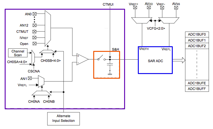
The PIC32's Analog to Digital Converter (ADC) can be challenging to configure for first-time users. The extensive range of configuration options available for the PIC peripherals can be overwhelming. This tutorial aims to assist users in navigating these complexities. The...
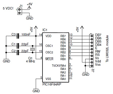
This document discusses an older LM032L LCD module from Hitachi. It details the process of making the module operational with a PIC 16F84A microcontroller. The module is capable of displaying two lines with 20 characters each. The initial step...

This circuit is similar to the one found in the Single Buss 1V/Octave Keyboard Controller. Refer to the circuit description there for more details. This board includes additional resistors used in the keyboard voltage divider. In a typical keyboard,...
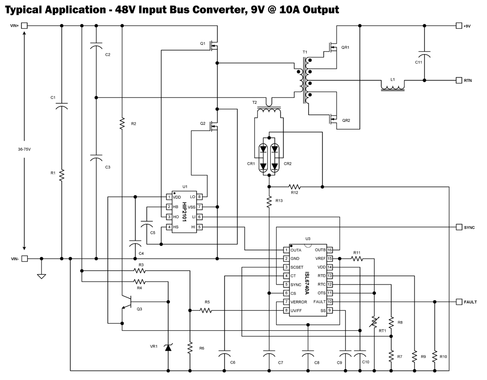
The ISL6740A is an enhanced PWM controller that incorporates built-in voltage feed forward functionality. It is pin and feature compatible with the ISL6740 double-ended pulse width modulation (PWM) voltage-mode controller, facilitating straightforward drop-in replacement in existing designs. Voltage feed...
This ISP programmer can be utilized for in-system programming or as a standalone SPI programmer for Atmel ISP programmable devices. The programming interface is compatible with STK200 ISP programmer hardware, allowing users of STK200 to employ the software, which...
The filter consisting of resistors R1, R2, and capacitor C1 integrates the PWM waveform. The purpose of the operational amplifier appears to be that of a non-inverting amplifier, with the gain determined by resistors R6 and R7. However, the...