
Pwm motor speed control
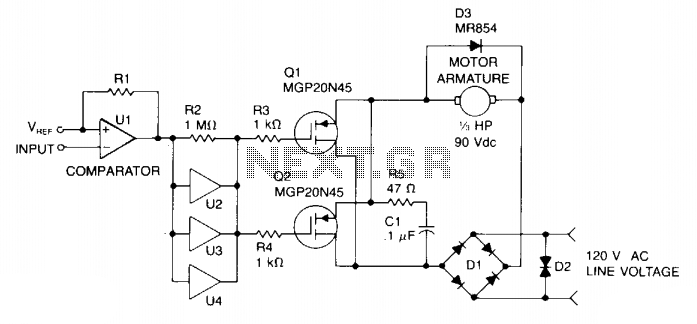
The described circuit operates by utilizing pulse width modulation to control the speed of a DC motor. The MGP20N45 TMOS devices serve as high-efficiency switches that modulate the power delivered to the motor based on the PWM signal's duty cycle. The PWM signal is generated by a microprocessor or digital logic circuit, which allows for precise control of the motor speed.
The comparator U1 is essential for comparing the PWM signal with a reference voltage, ensuring accurate timing and switching of the TMOS devices. The output from U1 is then sent to a set of paralleled inverters (U2, U3, and U4), which amplify the signal to ensure that the gates of the TMOS devices receive a sufficient drive voltage. This configuration helps in achieving rapid switching and minimizes power loss during operation.
The bridge rectifier D1 converts the AC input voltage to a DC output, ensuring that the motor receives a consistent power supply. The filtering components, R5 and C1, smooth out the rectified voltage, providing a stable DC supply to the motor and reducing voltage ripple.
The inclusion of the free-wheeling diode D3 is crucial for protecting the TMOS devices from voltage spikes that may occur when the motor is switched off. This diode allows for the safe dissipation of inductive kickback generated by the motor's coils, thereby preventing potential damage to the switching devices.
Furthermore, the back-to-back zener diode D2 serves as a protective measure against transient voltage spikes and high voltage surges that could otherwise exceed the voltage ratings of the components in the circuit. By clamping excessive voltages, D2 ensures the longevity and reliability of the circuit under varying operational conditions.
Overall, this circuit design effectively integrates PWM control, robust voltage regulation, and protective components to achieve efficient motor speed control while safeguarding against potential electrical hazards.Speed control is accomplished by pulse width modulating the gates of two MGP20N45 TMOS devices. Therefore, motor speed is proportional to the pulse width of the incoming digital signal, which can be generated by a microprocessor or digital logic. The incoming signal is applied to comparator Ul, then to paralleled inverters U2, U3, and U4 that drive the two TMOS devices, which, in turn, control power applied to the motor armature.
Bridge rectifier Dl supplies fullwave power that is filtered by R5 and Cl. Free-wheeling diode D3 (MR854) prevents high voltage across Ql and Q2. A back-to-back zener diode, D2, protects against transients and high voltage surges. 🔗 External reference
Related Circuits
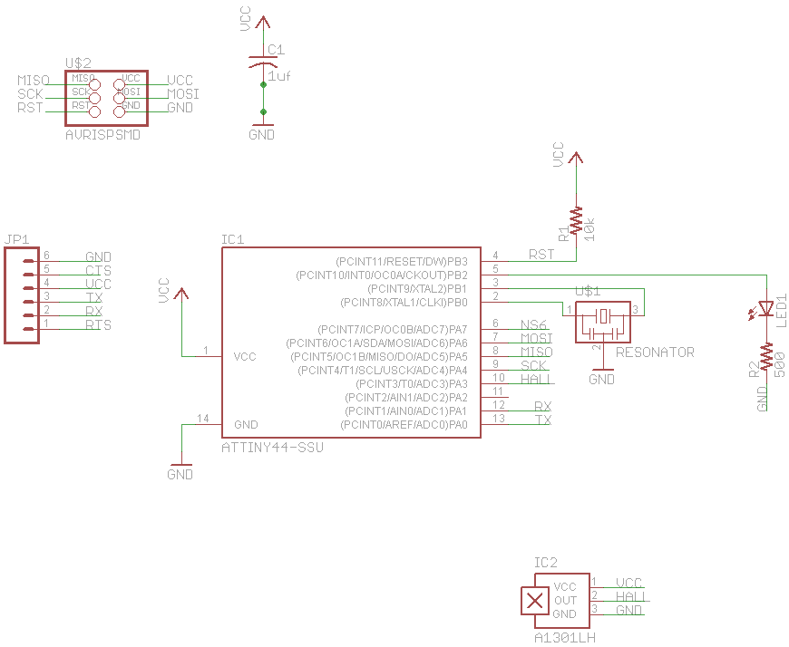
The final project involves cycling rollers that require a method to sense the rotational speed of one of the rollers. Speed sensors on bicycles typically function by detecting a magnet attached to a spoke on one of the wheels...
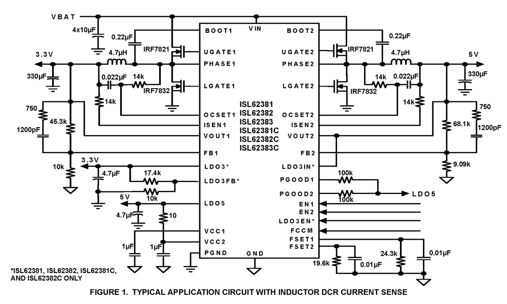
The ISL62381, ISL62382, ISL62383, ISL62381C, ISL62382C, and ISL62383C family of controllers generate supply voltages for battery-powered systems. These controllers include two pulse-width modulation (PWM) controllers, adjustable from 0.6V to 5.5V, and two linear regulators, LDO5 and LDO3, that generate...
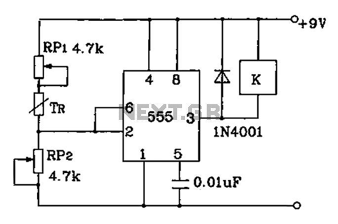
Adjust RP1 and RP2 to set the preset temperature control point. The 555 circuit is configured as a Schmitt inverter circuit that automatically controls a relay device. This forms part of the T-121 temperature control circuit, which includes a...
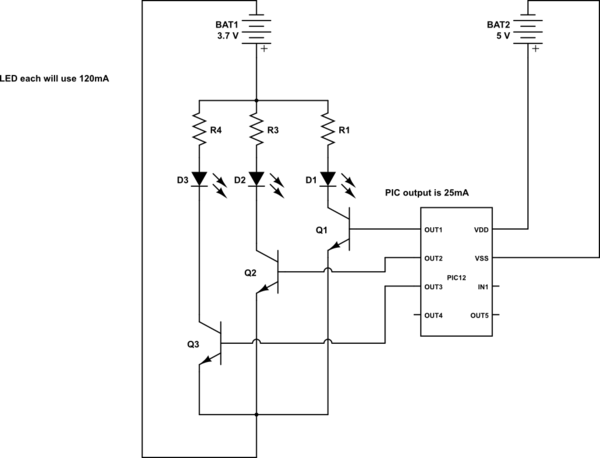
This is a conceptual schema utilizing a PIC12 microcontroller to control the blinking of three LEDs, each exhibiting different blinking patterns. There are several questions that need to be addressed. The circuit design involves a PIC12 microcontroller, which is a...
To capture high-speed photographs, a fast shutter or light source is essential. This project involved examining a commercial flash unit to analyze its light profile. A phototransistor was connected in an emitter follower configuration with a low impedance emitter...
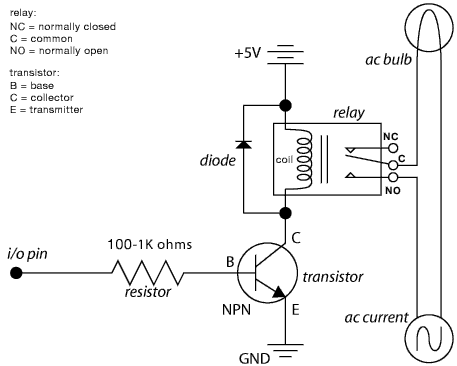
The schematic illustrates the Relay Wiring Circuit Diagram used to control an air conditioner or other high-current devices via a microcontroller. The relay wiring circuit serves as an interface between low-voltage microcontroller signals and high-voltage appliances, such as air conditioners....