
What transistor to use when building a simple MCU controlled LED blinking circuit
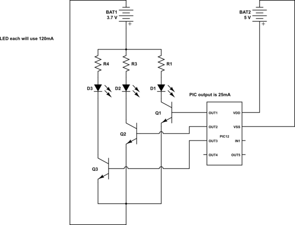
The circuit design involves a PIC12 microcontroller, which is a compact and efficient device suitable for controlling simple tasks such as LED blinking. The microcontroller will be programmed to generate distinct timing sequences for each of the three LEDs, allowing for varied blinking patterns.
The schematic will include the following components:
1. **Microcontroller (PIC12)**: The central processing unit that executes the blinking patterns. It will be powered by a suitable voltage source, typically 5V DC.
2. **LEDs**: Three individual light-emitting diodes, each connected to a different output pin of the PIC12. Resistors will be included in series with each LED to limit the current and prevent damage. The values of these resistors should be calculated based on the LED specifications and the supply voltage.
3. **Resistors**: Each LED will require a current-limiting resistor, calculated using Ohm's Law. For example, if an LED has a forward voltage of 2V and a desired current of 20mA, a resistor value of approximately 150 ohms would be appropriate when using a 5V supply.
4. **Programming Interface**: To load the blinking pattern program onto the PIC12, a programming interface (such as ICSP - In-Circuit Serial Programming) may be included in the schematic. This allows for easy updates to the microcontroller's firmware.
5. **Power Supply**: A stable power source will be required to ensure consistent operation of the microcontroller and LEDs. This can be a battery or a regulated power supply, providing the necessary voltage and current.
The blinking patterns for the LEDs can be programmed using a simple loop structure in the firmware. Different delays can be implemented to achieve various blinking effects, such as alternating flashes, simultaneous blinking, or sequential lighting.
Overall, this circuit provides a straightforward yet effective means of demonstrating microcontroller capabilities in controlling multiple outputs with varying behaviors. The design can be expanded or modified to include additional features such as user inputs or more complex patterns as needed.This is my conceptual schema to use a PIC12 to control the blinking of 3 LEDs with different blinking patterns. I have a few questions that would like to ask. 🔗 External reference
Related Circuits
A peak level indicator when a signal exceeds a certain maximum value. It can be quite useful, for instance, with tape recorders, mixing consoles etc. One of the most important requirements of a peak level indicator is that it...
Adjustable 1.5 - 35 V DC Regulated Power Supply Circuit Diagram. This diagram includes three circuit designs and is categorized under Power Supply. For more information, refer to the detailed post titled "Adjustable 1.5 - 35 V DC Regulated...
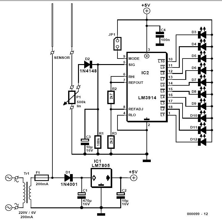
For individuals who prefer not to engage directly with soil, this simple soil moisture tester efficiently assesses the condition of their plants and the level of care they require. The soil moisture tester is a device designed to measure the...
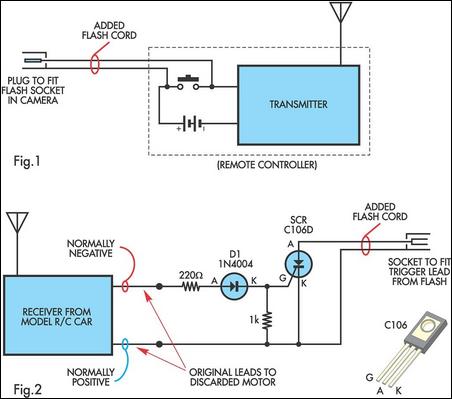
A radio-controlled electronic flash is an essential tool for any photographer's kit, frequently utilized by professionals. For instance, a wedding photographer may position one behind the bride to illuminate her gown and veil without visible wires in the shot....
While many power supplies can be set to limit their output current to a defined level to protect the circuit they are powering, no such protection is available. To enhance the safety and reliability of electronic circuits, it is crucial...
This interface design has a long history. It is the first microcontroller design initiated in early 1998, which has evolved over the years. Initially, the schematic diagram for the first prototype was drafted in 1998, and it later became...
Warning: include(partials/cookie-banner.php): Failed to open stream: Permission denied in /var/www/html/nextgr/view-circuit.php on line 713
Warning: include(): Failed opening 'partials/cookie-banner.php' for inclusion (include_path='.:/usr/share/php') in /var/www/html/nextgr/view-circuit.php on line 713