
5-Volt RelayCircuit for Controlling AC Current
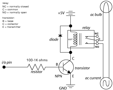
The relay wiring circuit serves as an interface between low-voltage microcontroller signals and high-voltage appliances, such as air conditioners. This circuit typically consists of a relay module, which includes an electromagnetic switch capable of handling high current. The microcontroller outputs a control signal, often a digital HIGH or LOW, to the relay's input, activating or deactivating the relay coil.
When the microcontroller sends a HIGH signal to the relay, current flows through the relay coil, creating a magnetic field that closes the switch contacts. This action connects the high-voltage power supply to the load—in this case, the air conditioner—allowing it to operate. Conversely, when the microcontroller outputs a LOW signal, the relay coil is de-energized, the magnetic field collapses, and the switch contacts open, disconnecting the power supply from the load.
To ensure safe operation, the circuit may include protective components such as diodes across the relay coil to prevent back EMF when the relay is switched off, as well as fuses or circuit breakers to protect against overcurrent situations. Additionally, opto-isolators may be used to provide electrical isolation between the microcontroller and the high-voltage circuit, enhancing safety and reducing the risk of damage to sensitive components.
The schematic should clearly indicate the connections between the microcontroller, relay module, power supply, and load, along with any necessary components for protection and isolation. Proper labeling of each component and connection will facilitate understanding and implementation of the circuit, ensuring reliable control of high-current devices.The following schematic shows the Relay Wiring Circuit Diagram for controlling an Air Conditioner or other higher high-current device from a microcontroller.. 🔗 External reference
Related Circuits
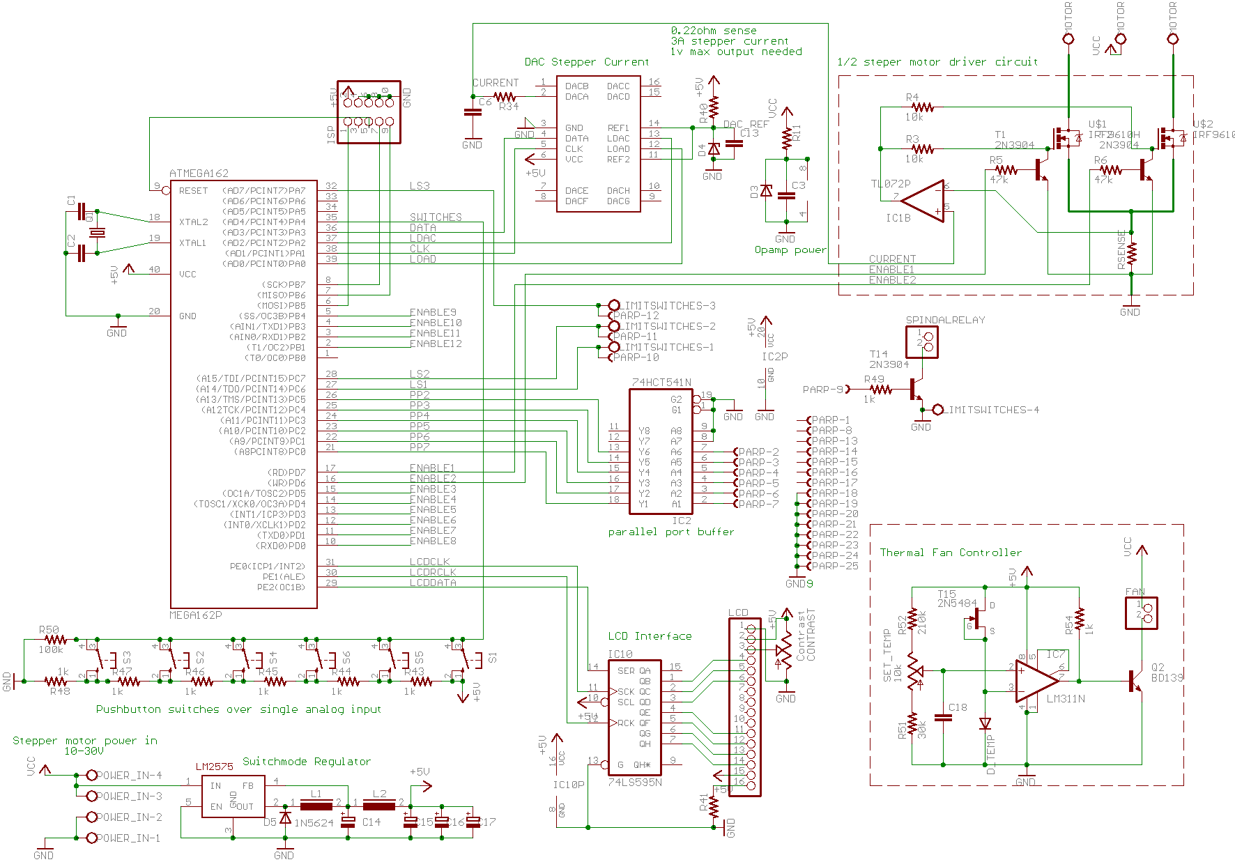
A basic CNC machine was built for a university project, and the completed machine will undergo upgrades over the coming months. The plan includes replacing the small 48-step stepper motors with larger 200-step motors to enhance performance. The project involves...
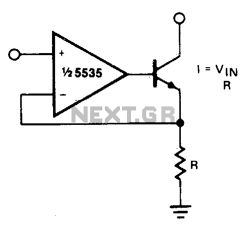
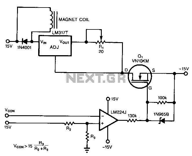
The output current is Iqut = Vin/R. For negative currents, a PNP transistor can be utilized, and for improved accuracy, a Darlington pair may be substituted for the transistor. With careful design, this circuit can be employed to control...
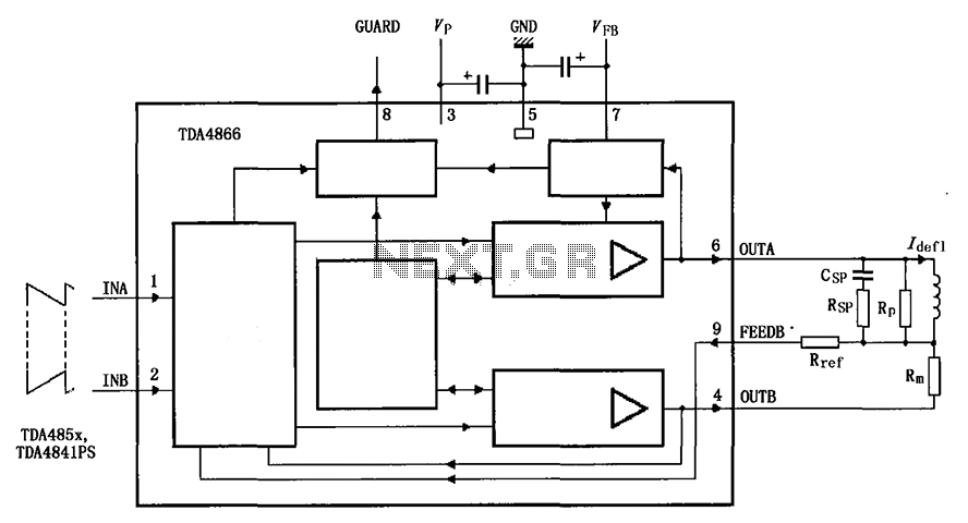
The TDA4866 is a 90-color power amplifier designed for vertical deflection systems, operating at a frequency range of 50 to 160 Hz. The CRMM circuit is implemented to ensure a high current drive input. The amplifier features a dual...
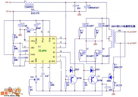
Charging any type of rechargeable battery is critical and requires attention, particularly regarding the current or rate at which the battery is charged. This factor is essential for maintaining the battery's lifespan and efficiency over time. The circuit diagram...
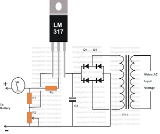
The circuit powers the load through the input of the regulator rather than its output. Due to the presence of a constant dummy load (R1) at the regulator's output, it attempts to draw a constant amount of current, regardless...
An operational amplifier circuit can provide a constant voltage source with a high amplification factor and substantial load current. Even with significant variations in circuit parameters, the output voltage maintains high precision. The output current limit is managed by...