
two speed contactor dc motor controller

Switch S1 closes relay K3, causing motor M1 to operate. Switch S2 activates relays K1 and K2, reconfiguring the batteries for series operation and enabling M1 to run at high speed. Batteries B1 and B2 should be selected based on the current requirements of motor M1. Often, sealed lead-acid batteries can be found at local suppliers at low prices, making them suitable for applications such as scooters and go-karts. It is important to note that in series mode, all three relays draw power from battery B2. This is due to the relays having 12V coils, making it impossible to switch the batteries from series to parallel while simultaneously supplying power to the coils. Consequently, B2 may be discharged slightly before B1. This should generally not pose a problem unless the batteries are completely drained. Draining a battery to a dead state is not advisable and should be avoided. If desired, a small 12V battery can be used to independently power the relays. Additionally, two more speeds can be added to this controller by utilizing the schematic connections at points A and B shown in the controller schematic.
The contactor controller circuit employs three relays, each designed to handle the switching of the motor's power supply and the battery configuration. Relay K1 and K2 work in tandem to switch between series and parallel configurations, while relay K3 controls the motor operation.
The circuit is powered by two 12V batteries, B1 and B2, which are selected based on the motor's current draw. In the parallel configuration, the batteries are connected to provide a higher current output, allowing for a gradual acceleration of the motor. In contrast, when the batteries are switched to series, the voltage is doubled, enabling the motor to reach higher speeds quickly.
To ensure that the relays operate correctly, they are connected to the corresponding switches S1 and S2. S1 is used to engage relay K3, which activates the motor, while S2 engages K1 and K2 to change the battery configuration. The design also incorporates a mechanism to prevent simultaneous activation of series and parallel configurations, which would otherwise lead to potential damage.
The choice of sealed lead-acid batteries is practical due to their availability and cost-effectiveness. These batteries are well-suited for applications requiring moderate power and can be easily sourced from local suppliers.
It is crucial to monitor the battery levels to prevent complete discharge, as this can lead to reduced battery life and performance issues. A small separate 12V battery can be utilized to power the relays independently, ensuring that the main batteries are preserved for motor operation.
In conclusion, the contactor controller provides a simple yet effective method for controlling motor speed and operation in electric scooters and similar applications, with the flexibility of adjusting battery configurations for optimal performance.The simplest of all motor controllers (besides a beeline on/off switch) is the contactor controller. I advised this contactor ambassador for use in my electric scooter project. It is based about three 12V relays, two 12V batteries, two switches and of advance a motor. Having no silicon to fry , it is absolutely reliable and robust. A contactor a mbassador works by rearranging the two (or more) accumulation batteries amid alternation and parallel. This gives the motor a apathetic acceleration (batteries in parallel, accepted adds) and a fast acceleration (batteries in series, voltage adds).
This assures that both batteries are absolved equally. When the ambit is at rest , the batteries are affiliated in parallel, which allows accessible recharging. 1. S1 closes K3 and appropriately causes M1 to operate. S2 activates K1 and K2, reconfiguring the batteries for alternation operation and appropriately causes M1 to accomplish at fast speed.
2. B1 and B2 should be called based on the accepted requirements of M1. Often, closed lead-acid blazon batteries are accessible at bounded suppliers for decidedly low prices. These batteries are ideal for things such as scooters, go-karts, etc. 5. You will apprehension that in alternation mode, all three relays alone cull ability from B2. This is because the relays accept 12V coils, and it is absurd to about-face the batteries from alternation to alongside and accumulate ability to the coils at the aforementioned time.
This does, however, beggarly that B2 is absolved slighty afore B1. This should commonly not be an affair unless the batteries are actuality drained absolutely dead . Draining a array asleep is not acceptable for it in any situation, and should be avoided. If you wish, you can use a baby 12V array to run the relays separately. 6. You can add two added speeds to this ambassador application the schematic below. It connects at credibility A and B apparent aloft on the ambassador schematic. 🔗 External reference
Related Circuits
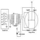
The simplest method to drive a stepper motor with a lower current rating is by utilizing the ULN2003. The ULN2003 consists of seven Darlington transistors and can handle up to 500mA per channel, with an internal voltage drop of...
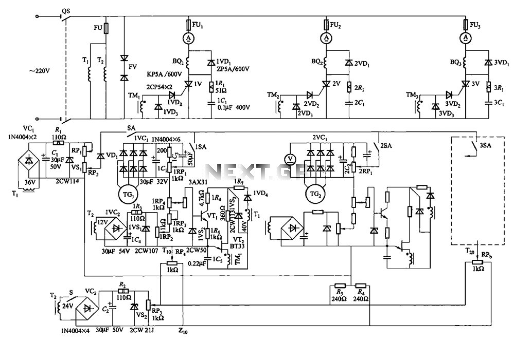
Collaboration with the dancers balanced bridge long on the porcelain unit. A sync adjustment rheostat speed control system is shown in Figure 3. The principle of speed control for electro-magnetic and photoelectric dancers is similar. The main motor (BQ2)...
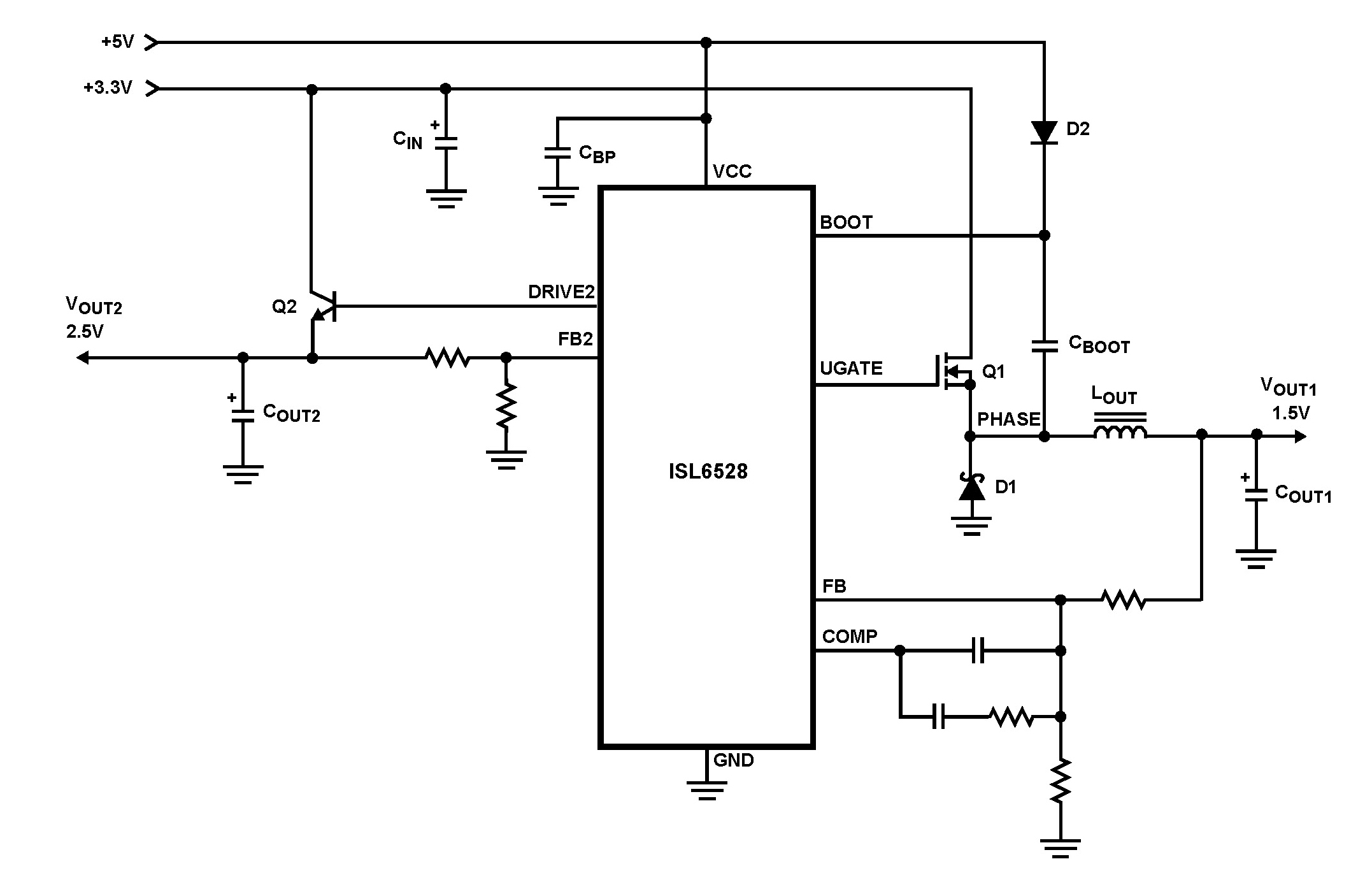
The ISL6528 offers power control and protection for two output voltages in high-performance graphics cards and other embedded processor applications. This dual-output controller drives an N-Channel MOSFET in a standard buck topology and an NPN pass transistor in a...
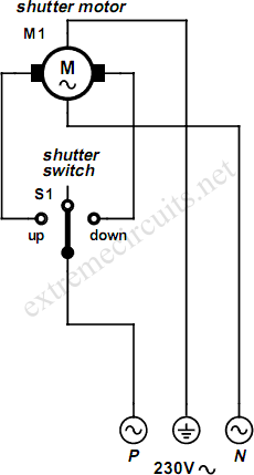
An electrically operated rolling shutter typically features a standard control panel equipped with a three-position switch that allows for up, down, and stop functions. The electrically operated rolling shutter system is designed to provide convenient control over the opening...
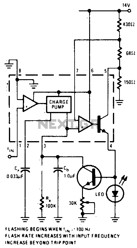
An operational amplifier (op-amp) comparator is utilized to compare the output of a converter with a direct current (DC) threshold voltage. The circuit activates an LED when the input frequency surpasses 100 Hz. As the frequency increases, the average...
Automatic door control systems typically have a high market price for finished products. The proposed method is suitable for home use, utilizing easily accessible components. This design is ideal for those interested in creating their own automatic door system....