
Alarm Control Electronic Keypad Project
The circuit utilizes a CMOS 4081 quad 2-input AND gate configuration to create a secure alarm system. Each input key is strategically assigned to specific gates, enabling a sequential activation process that ensures only the correct combination deactivates the alarm. The design leverages the properties of the AND gate, where the output is HIGH only when all inputs are HIGH, effectively creating a layered security mechanism.
The alarm system's operation begins with pressing the key connected to pin E, which initiates the circuit by allowing current to flow through R1 and D1, activating Q5. The relay is energized, and the alarm is set in motion. The inclusion of resistors R2, R3, R5, and R8 ensures that each gate remains enabled until the correct sequence of keys is entered. If at any point an incorrect key is pressed, the system resets, preventing unauthorized access.
The circuit is designed with flexibility in mind, allowing for a variety of keypads, including custom designs. The requirement for a common terminal simplifies the wiring process, ensuring that the alarm system can be easily implemented. The potential for over 10,000 unique combinations significantly enhances security, making it difficult for an intruder to guess the correct sequence.
For added security, the architecture can be expanded by integrating additional 4081 ICs to create more complex combinations or by utilizing larger keypads with additional incorrect key options. This adaptability makes the circuit suitable for various applications, from home security systems to more specialized uses. The careful selection of components, including transistors and resistors, ensures reliable operation while maintaining a straightforward design that can be easily replicated or modified.The IC is a quad 2 input "AND" gate, a CMOS 4081. These gates only produce a HIGH output, when BOTH the inputs are HIGH. When the key wired to `E` is pressed, current through R1 and D1 switches Q5 on. The relay energizes; and Q5 is `latched on` by R8. Thus, the Alarm is set by pressing a single key, say one of the two non-numeric symbols. The alar m will switch off when the 4 keys connected to "A, B, C, D" are pushed in the right order. The circuit works because each gate `Stands` upon its predecessor. If any key other than the correct key is pushed, then gate 1 is knocked out of the stack, and the code entry fails. Pin 1 is held high by R4. This `Enables` gate 1; and when button `A` is pressed, the output at pin 3 will go high. This output does two jobs. It locks itself `ON` through R2 and it `Enables` gate 2, by taking pin 5, high. Now, if `B` is pressed, the output of gate 2, at pin 4 will go high. This output does two jobs. It locks itself `ON` through R3 and it `Enables` gate 3 by taking pin 12 high. Now, if `C` is pressed, the output of gate 3 will lock itself `ON` through R5 and, by taking pin 8 high, `Enable` gate 4.
Pressing `D` causes gate 4 to do the same thing; only this time its output, at pin 10, turns Q4 `ON`. This takes the base of Q5 to ground, switching it off and letting the relay drop out. This switches the alarm off. Any keys not connected to `A B C D E` are wired to the base of Q1. Whenever `E` or one of these other keys is pressed, pin 1 is taken low and the circuit is reset. In addition, if `C` or `D` is pressed out of sequence, then Q2 or Q3 will take pin 1 low and the circuit will reset.
Thus nothing happens until `A` is pressed. Then if any key other than `B` is pressed, the circuit will reset. The Keypad needs to be the kind with a common terminal and a separate connection to each key. On a 12 key pad, look for 13 terminals. The matrix type with 7 terminals will NOT do. Wire the common to R1 and your chosen code to `A B C D`. Wire `E` to the key you want to use to switch the alarm on. All the rest go to the base of Q1. The diagram should give you a rough guide to the layout of the components, if you are using a strip board. The code you choose can include the non-numeric symbols. In fact, you do not have to use a numeric keypad at all, or you could make your own keypad. I haven`t calculated the number of combinations of codes available, but it should be in excess of 10 000 with a 12 key pad; and, after all, any potential intruder will be ignorant of the circuit`s limitations.
Of Course, if you must have a more secure code, I can think of no reason why you shouldn`t add another 4081 and continue the process of enabling subsequent gates. Or you could simply use a bigger keypad with more "WRONG" keys. Any small audio transistors should do. The 27k resistors could be replaced with values up to 100k. And the only requirements for the 4k7 resistors is that they protect the junctions while providing enough current to turn the transistors fully on.
🔗 External reference
Related Circuits
Stand-alone, 9V battery powered unit, three-level input selector, three-band tone control. This preamplifier was designed as a stand-alone portable unit. The described preamplifier is a compact, battery-operated device that operates on a 9V power supply, making it suitable for portable...

The circuit diagram represents a brushless DC motor driving circuit designed for a 45V/8A application. It features an open voltage-controlled design that allows for speed adjustment through an external potentiometer connected to a PWM duty cycle. The diagram illustrates...
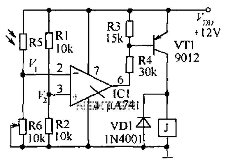
The circuit functions as a precision bright light control circuit, operating independently of variations in power supply voltage and ambient temperature. Resistors R1, R2, R6, and the photosensitive resistor R5 form a two-arm Wheatstone bridge. The precision bright light control...
The Clock Controller was designed as an exemplary application of the C programming language to manage timer0 interrupts, control a 7-segment LED display, and perform keypad scanning. It offers a 1-bit sink current output suitable for driving devices such...
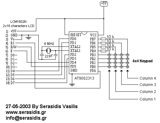
This circuit is designed for experiments using the AT90S2313 microcontroller, a 2x16 LCD display, and a 4x4 keypad. It operates with a clock based on a 4 MHz crystal, although any crystal between 1-4 MHz can be utilized. The...
This design is based on one published by Milan Lulic in the German magazine elektroModell. Mr. Lulic's design is for surface mount technology (SMT) construction, whereas mine uses standard off-the-shelf components, and is therefore better suited to construction by...