
PWM sound Tutorial
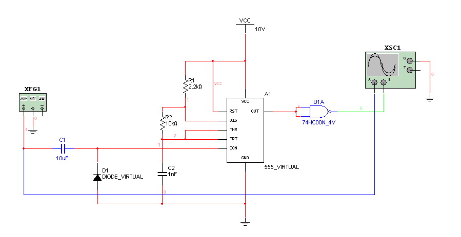
The circuit described utilizes an Arduino microcontroller to generate sound through Pulse Width Modulation (PWM). The PWM output pin from the Arduino is programmed to switch rapidly between LOW and HIGH states, producing a square wave signal. The frequency of this square wave can be adjusted within the audible range of 20 Hz to 20 kHz, allowing for the generation of various tones.
In the first output scheme, the Piezo Speaker is directly connected to the PWM pin. This configuration is simple and effective for generating basic tones, although the sound quality and frequency response will depend on the specifications of the Piezo Speaker used.
The second method introduces a low-pass filter, which is essential for transforming the square wave into a smoother line-level audio signal. This filter typically consists of resistors and capacitors that attenuate the higher frequency components of the square wave, resulting in a more sinusoidal waveform. This output can then be connected to standard audio equipment, such as amplifiers or mixers, allowing for broader applications in audio projects.
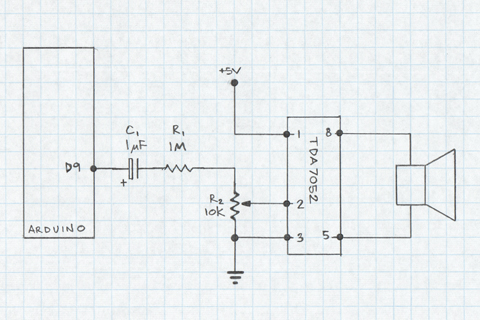
The third scheme incorporates a TDA7052 audio amplifier, which is designed for low-power audio amplification. The TDA7052 chip is connected to the output of the low-pass filter and features built-in volume control. This setup allows for the amplification of the audio signal to drive a small 8-ohm speaker, providing a more robust sound output suitable for various applications. The combination of the Arduino, low-pass filter, and TDA7052 amplifier creates a versatile audio generation system that can be tailored to different sound requirements.Here we demonstrate the use of an Arduino PWM output pin to generate sound. The output pin can be toggled very quickly from LOW to HIGH generating a square wave. If the frequency of this square wave is within the range of 20-20, 00Hz and sent directly into a Piezo Speaker, an audible tone will be produced (in reality, the range of output is limited by the specs of the speaker and does not cover the entire audible frequency range. ) This tutorial covers three sound output schemes: first is the method with the Piezo Speaker connected directly to the Arduino output pin. The second uses a low pass filter to transform the square wave to a line level signal that can be used with standard audio equipment.
The third output scheme uses a TDA7052 amplifier (8-DIP) chip with volume control and sends the audio signal into a small 8 OHM speaker. 🔗 External reference
Related Circuits
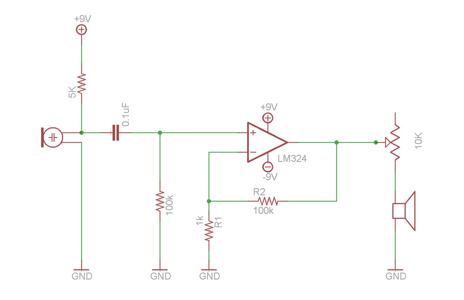
This video demonstrates the fundamentals of operational amplifiers (op amps) and includes an example circuit that amplifies a small microphone signal to make it audible through earbuds. The circuit utilizes the LM324 quad op amp integrated circuit (IC). The described...
This document is a revised version of an article titled "Better Bachmann Sound For Under A Buck," which was published in the February 1998 issue of Garden Railways Magazine. It does not include editorial changes or additional artwork that...
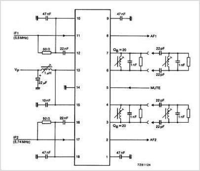
The TDA3567 is a monolithic integrated decoder designed for the NTSC color television standards. It incorporates all the necessary functions for the demodulation of NTSC signals. Additionally, it features a luminance amplifier and an RGB matrix amplifier. These amplifiers...
Hello everyone. I need some help. I have constructed a PWM and PPM circuit. The output is functioning smoothly, but I am experiencing some problems and I am not very experienced. The PWM (Pulse Width Modulation) and PPM (Pulse Position...
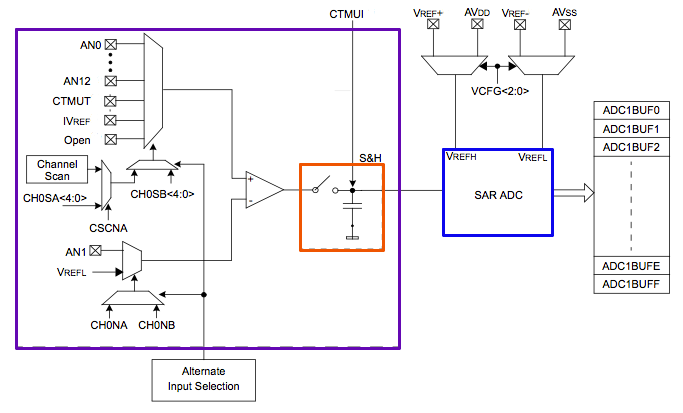
The PIC32's Analog to Digital Converter (ADC) can be challenging to configure for first-time users. The extensive range of configuration options available for the PIC peripherals can be overwhelming. This tutorial aims to assist users in navigating these complexities. The...
This circuit generates a two-tone effect similar to the sound of a cuckoo. It can be utilized for doorbells or other applications due to its integrated audio amplifier and loudspeaker. The circuit is designed to produce a distinctive two-tone sound,...