
pwm Why is the MOSFET driver in this circuit dying
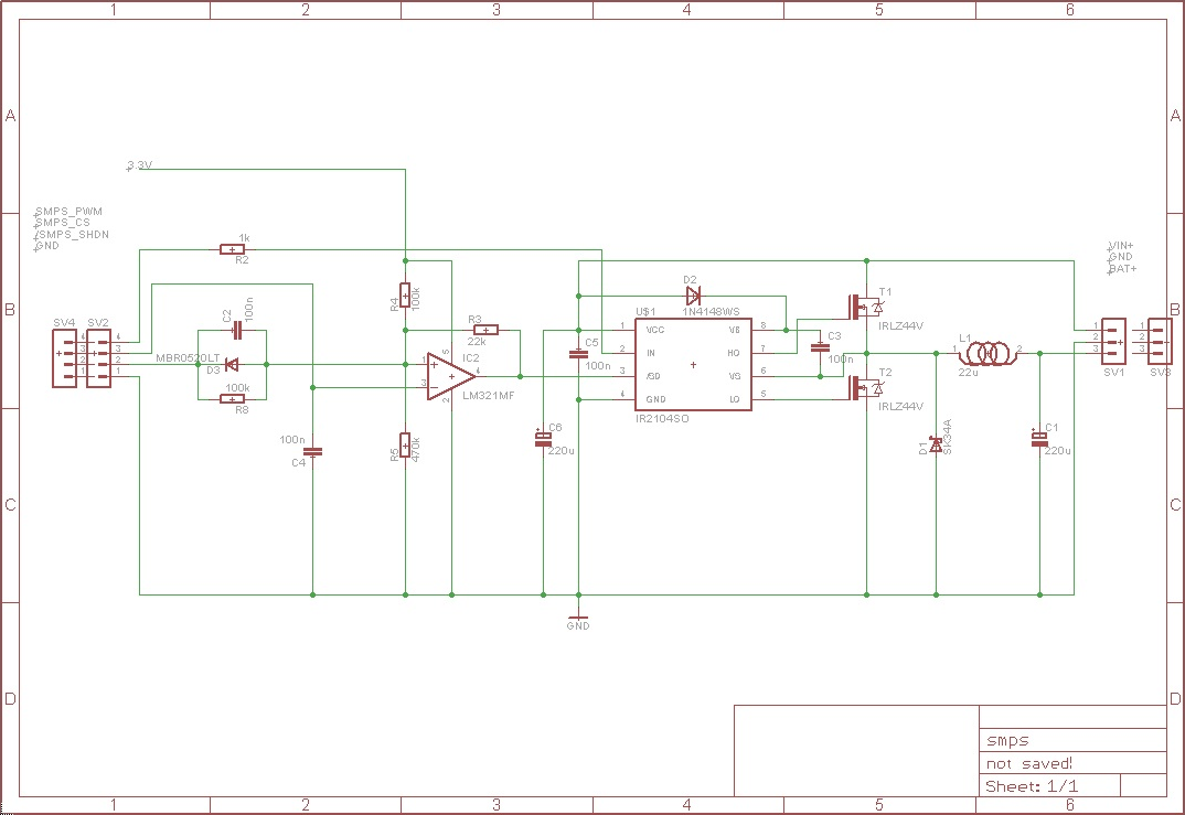
The circuit design incorporates a Switch Mode Power Supply (SMPS) that utilizes two MOSFETs, which are essential for efficient voltage conversion. The IR2104 driver plays a critical role in managing the switching of these MOSFETs, enabling rapid transitions that are necessary for the SMPS operation. The LM321 is used as a latch, providing a feedback mechanism that allows the MCU to monitor the state of the IR2104 and control its operation based on system requirements.
The left connector serves as the interface for the MCU, facilitating communication and control signals, while the right connector is responsible for delivering the necessary power lines to the circuit. The PWM signal generated for the IR2104 is crucial for controlling the duty cycle of the MOSFETs, thereby regulating the output voltage to the battery. The inclusion of a current sense pin (CS) enhances safety by providing the capability to disable the IR2104 if excessive current is detected, preventing potential damage to the circuit components.
The circuit has been tested with a purely resistive load, demonstrating functionality; however, complications arise when a battery is introduced. The driver experiences failure under these conditions, although the MOSFETs remain operational, indicating that the issue may lie within the driver circuitry rather than the power switching elements themselves. The power supply is designed to limit current to 30mA, which serves as a protective measure against overcurrent conditions.
The power regulation loop that feeds into the PWM signal is noted to be simplistic, utilizing a basic ramp algorithm that may not provide the responsiveness required for dynamic load conditions. This lack of sophistication in the control loop could contribute to the driver’s failure, especially under high duty cycle conditions. It is hypothesized that a 100% duty cycle may cause the upper MOSFET to remain continuously closed, potentially leading to thermal or electrical stress that could compromise the integrity of the driver.
Further investigation into the behavior of the MOSFETs under high voltage conditions is warranted, as there is a possibility that a MOSFET bridge configuration could unintentionally cause damage through gate voltage spikes, despite appearing functional during standard testing conditions. This highlights the importance of thorough testing and validation of circuit components under various operational scenarios to ensure reliability and performance.The circuit takes Vin, passes it through a SMPS with two MOSFETS (driven by the ir2104 that dies) and into Bat+. The LM321 is just a latch that allow the MCU to control and read the ir2104). The connector in the left comes from the MCU, the right one holds the power lines. PWM(PWM signal for the 2104) CS (current sense pin, for safety -it can stop the ir2104-) SHDN (a shutdown signal) Using a purely resistive load instead of the battery works. Then the battery is connected and the driver gives up. The MOSFET doesn`t die, though. This using a current-limited (to 30mA) power supply. There is a power regulation loop (that feeds the PWM that goes into SMPS_PWM) which is not really good or responsive (it is a very simple ramp algo), but even then, why would the driver die One running theory is that, if the PWM were to be 100% you`d have an upper MOSFET that`s permanently closed, and that`d be a problem, but I don`t see why (and sure a 100% duty cycle won`t work in a charge pump driver, but that should affect the MOSFET, not the driver. ) The MOSFETs are not broken in any visible way. Could a MOSFET bridge so it would kill something through its gate at a high voltage but look okay when testing
🔗 External reference
Related Circuits
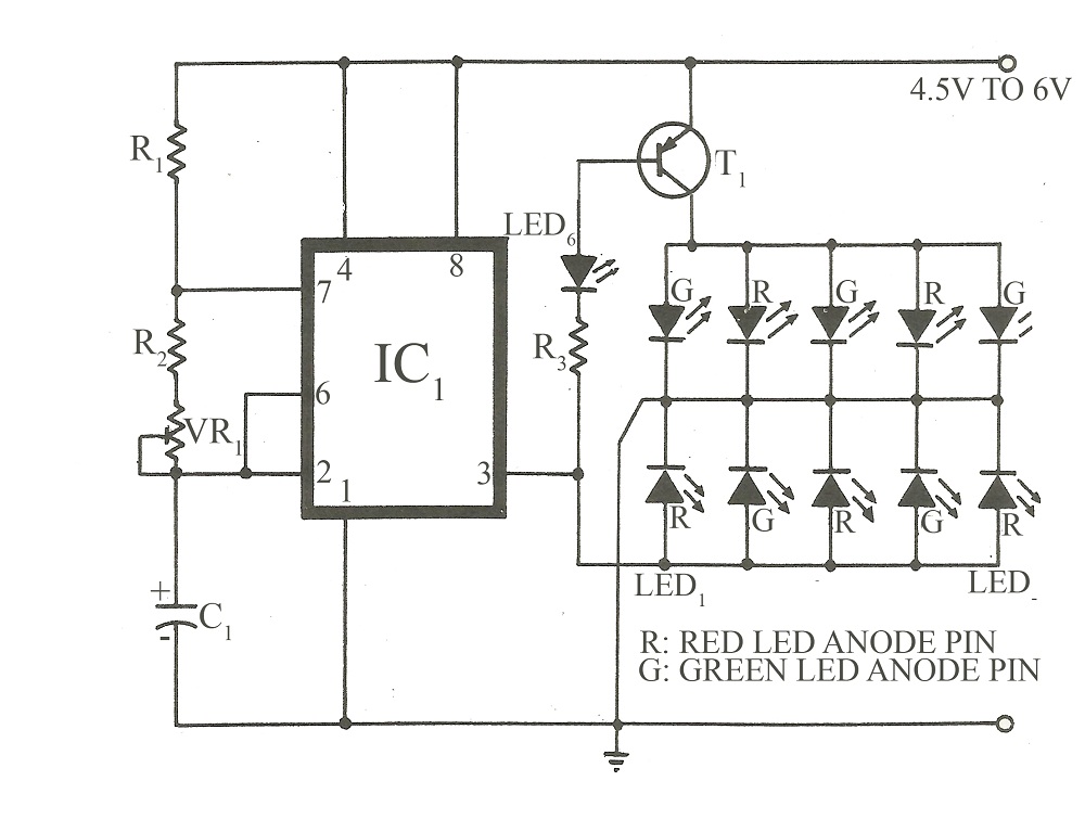
This circuit is similar to various published flasher circuits that utilize the IC 555 as a free-running multivibrator. The primary distinction is in the method of flashing bi-color LEDs. When the output at pin 3 of the IC 555...

The accumulator charger circuit must provide a voltage that matches the specifications of the batteries being charged. For a 12-volt accumulator, the output voltage should not exceed 12 volts, nor should it fall significantly below this threshold. Failure to...
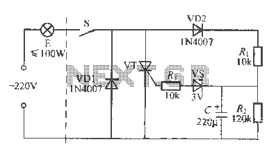
An incandescent lamp operates with a two-wire connection and features a life extension open circuit. It has a longer warm-up time compared to other types of lamps, resulting in a significant delay before illumination. Upon closing the switch, a...
Camping today often involves various electronic accessories for daily activities or entertainment. Typically, a portable battery charger and a power inverter are used to ensure a well-organized campsite where both adults and children can comfortably use their electronic devices....
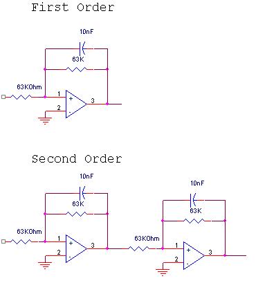
The circuit design involves a circular operational amplifier (op-amp) configuration that functions as a second-order low-pass and high-pass filter. The low-pass filter operates within a frequency range of 20 to 250 Hz, while details regarding the high-pass filter are...
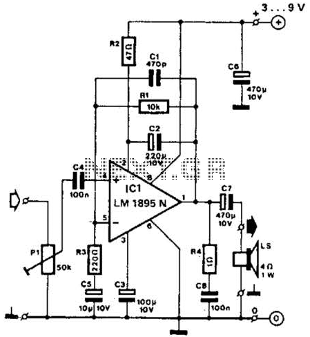
This amplifier operates with supply voltages ranging from 3 V to 9 V and can deliver an output power ranging from 100 mW to 1 W into a 4-ohm load. The bandwidth is approximately 20 kHz at a 3...