
Incandescent switching circuit
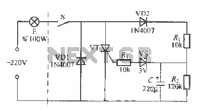
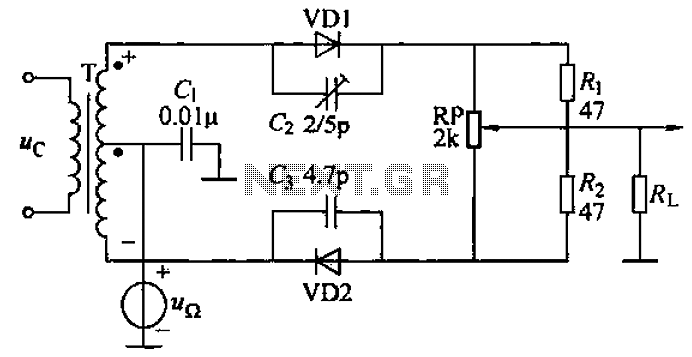
An incandescent lamp circuit designed for life extension utilizes a two-wire connection, integrating a warm-up mechanism to enhance operational longevity. The circuit operates on a standard 220V AC supply, where the switch closure initiates the flow of current. The negative half-cycle is conducted through diode VD1, energizing the lamp while placing it in a semi-pressure warm-up state.
During the positive half-cycle, the AC current is routed through diode VD2 and resistor R, which serves to charge the capacitor. The capacitor accumulates charge until the voltage across it surpasses the critical threshold of 3V. At this juncture, the voltage regulator tube and thyristor VT reach their breakdown voltage, allowing current to flow through the piezoelectric light bulb, thereby illuminating it.
The warm-up time is a crucial aspect of this circuit, primarily influenced by the values of the voltage regulator and the capacitor. Typically, the warm-up duration is approximately 2 seconds, which is essential for achieving optimal lamp performance. The thyristor VT, which can be triggered with a minimal current, can be substituted with components such as the 2N6565 or other similar micro-way thyristors. The circuit incorporates a 3V, 1/2W Zener diode as the voltage regulator, ensuring stable operation. Additional components do not have specific requirements, allowing for flexibility in the design while maintaining efficient functionality. This schematic design effectively balances performance and efficiency, making it suitable for applications where gradual illumination is preferred.Incandescent is a two-wire connection Life Extension open curse, i A warm-up time than its H K, so scorpionfish life bubble E is quite pregnant. After closing the Ji Guan S, 220V AC only negative 3F week by VD1, S E energizing the lamp made of light, this time for the semi-pressure warm-up state. AC positive half cycle through the VD2 and R. ., R dividing the capacitor (- charging until the voltage across C L rose to more than 3V , it will be behind the breakdown voltage regulator tube vs thyristor VT opened, then only Mou piezoelectric light bulb E electricity. Half way press Warm-up time mainly by the regulator and vs value of the capacitor C determines the capacity of the data when asked preheat icon about 2s .VT can trigger current small micro-way thyristor trigger, such as 2N6565, MC, R100 -type 8 etc.
.vs is 3V, 1 / 2W Zener diode. no special requirements other components.
Related Circuits
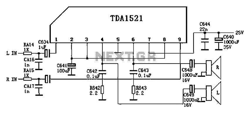
Color is often used in audio circuits like the TDA1521, which is derived from the Changhong C2191 model featuring an OTL two-channel connection. The pin functions and reference voltages for the TDA1521 are as follows: Pin 1: 11V -...
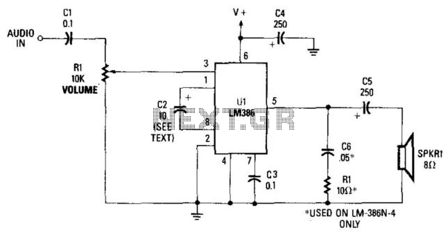
This simple receiver AF amplifier can supply several hundred milliwatts to an 8-ohm speaker. The gain is approximately 200X. If high gain is not required, C2 can be removed, resulting in a gain of 20. R1 and C6 are...
This is a 220V LED flasher circuit designed as a reliable alternative to thermally activated switches used for flashing Christmas tree lamps. It is a cost-effective and easy-to-assemble circuit. The components include R1 (100K), R2 (1K), R5 (1K), R3...
The danger always exists when fuel gases such as propane or natural gas are confined to a small area. The toxic gas alarm utilizes a tin-oxide semiconductor. A coil of thin wire is heated by a 12 V battery...
This is a subwoofer low-pass filter circuit, which is another variant based on the discharge from ST Microelectronics' TL062. The TL062 is a dual high-input impedance J-FET operational amplifier characterized by low power consumption and a high slew rate....
A common diode balanced modulator circuit is illustrated. It comprises two identical performance diodes and a center-tapped transformer configuration. The diodes used are VD1 and VD2, specifically 2AP9 models. The parameters for the circuit elements are detailed in FIG....
Warning: include(partials/cookie-banner.php): Failed to open stream: Permission denied in /var/www/html/nextgr/view-circuit.php on line 713
Warning: include(): Failed opening 'partials/cookie-banner.php' for inclusion (include_path='.:/usr/share/php') in /var/www/html/nextgr/view-circuit.php on line 713