
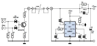
QRP CW TRANSCEIVER

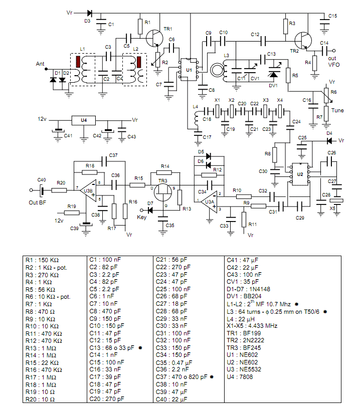
The described circuit is a compact and efficient VFO-controlled continuous wave (CW) transceiver designed for amateur radio operation on the 40 and 30-meter bands. With a power output of 3 Watts, this single-circuit board design emphasizes simplicity and performance, making it suitable for both beginners and experienced operators.
The core of the transceiver is the Voltage-Controlled Oscillator (VFO), which generates the transmit frequency. The oscillator is implemented using transistor Q1, which is configured with associated passive components to provide stable frequency generation. The design allows for precise tuning across the desired frequency range, ensuring reliable communication.
The direct-conversion receiver architecture enables the transceiver to demodulate incoming signals effectively. This method simplifies the design by allowing the use of a single mixer stage, where the received RF signals are mixed directly with the VFO output. The resulting baseband audio signal is then processed through audio filtering stages, which enhance the quality of the received audio and reduce unwanted noise.
Receiver Incremental Tuning (RIT) is incorporated into the design, allowing operators to fine-tune the received signal frequency without altering the main tuning setting. This feature is particularly useful in crowded band conditions where precise frequency adjustments are required to maintain clear communication with other stations.
The output audio is managed through a speaker-level volume control, which allows the operator to adjust the audio output to a comfortable listening level. This feature enhances usability, especially during extended operating sessions.
Transistor Q2 serves as a buffer, isolating the VFO oscillator from the rest of the circuit. This isolation is crucial in preventing loading effects that could destabilize the oscillator's frequency output, ensuring consistent performance and reliability.
Overall, this VFO-controlled CW transceiver represents an excellent choice for amateur radio enthusiasts looking for a straightforward yet effective solution for operating on the 40 and 30-meter bands. Its design prioritizes functionality while maintaining a compact footprint, making it an ideal project for those interested in building their own transceiver.This is a 3-W, single-circuit board, VFO-controlled CW transceiver for 40 or 30 me`ers, featuring a direct-conversion receiver with audio filtering, Receiver Incremental Tuning (RIT). and speaker level audio volume. The transmit frequency is generated by Q1 and its associated component in the VFO The buffer, Q2, isolates the oscillator from the other circuit..
🔗 External reference
Related Circuits
This circuit was designed to transmit commands over an LNB coaxial cable. An LNB (Low-Noise Block downconverter) is commonly used for satellite TV reception and is positioned at the focal point of a satellite dish. The circuit generates a...
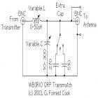
This circuit is for a QRP (low power) antenna tuner, a.k.a. a transmatch, for use in the short wave amateur radio bands from 3-30 MHz. It allows a wide variety of antennas to be connected to a low power...
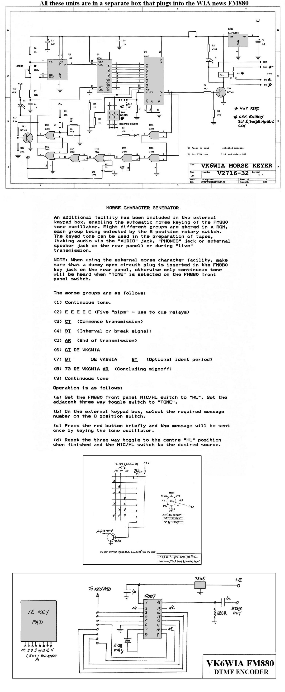
The unit is based on a PHILIPS FM880 link transceiver originally supplied to a Telecom Australia specification for telephone applications in remote areas of Australia. The FM880 is part of a family of equipment that includes the PHILIPS FM828/FM814...
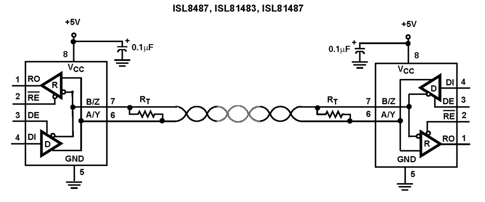
The Intersil RS-485/RS-422 devices are fractional unit load (UL), BiCMOS, 5V powered, single transceivers that comply with both RS-485 and RS-422 standards for balanced communication. This Intersil family is designed for 10% tolerance supplies (4.5V to 5.5V). The ISL81483...
This project describes a little QRP transceiver full legal power (5 W at 12 V) for the 40 meters band. The RIG may be built in a gradual manner; in fact, it is divided into two main modules, or...
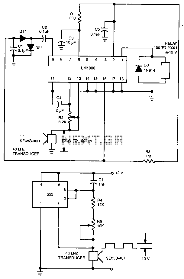
This ultrasonic transmit/receive circuit operates at 40 kHz. Control resistor R5 adjusts the frequency for optimal performance with the transducers used. The ultrasonic transmit/receive circuit designed to operate at a frequency of 40 kHz is essential for applications in distance...