
QRP Antenna Tuner
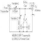
The QRP antenna tuner circuit, also known as a transmatch, is designed to match the impedance of various antennas to that of a low power transmitter operating in the shortwave amateur radio bands, specifically within the frequency range of 3 to 30 MHz. The primary objective of this circuit is to ensure that maximum power is delivered from the transmitter to the antenna, which enhances the overall efficiency of the radio communication.
The circuit typically incorporates variable inductors and capacitors that allow for fine-tuning of the impedance matching. The variable inductor is crucial for adjusting the reactance of the circuit, while the capacitors are used to tune the circuit to resonance at the desired operating frequency. The inclusion of a standing wave ratio (SWR) meter is essential as it provides real-time feedback on the performance of the antenna system, allowing the operator to optimize the tuning for minimal reflected power.
Construction of the tuner should be performed within an aluminum project box, which serves as both a protective enclosure and a means to minimize electromagnetic interference. It is important to drill appropriate holes in the box for mounting the components, ensuring that adequate spacing is maintained around each component to prevent RF arcing. Special care should be taken to insulate both sides of the variable inductor from the box to avoid unintended grounding or short circuits, which could adversely affect the performance of the tuner.
Overall, this QRP antenna tuner circuit is a versatile and essential tool for amateur radio operators seeking to maximize their low power transmission capabilities across a wide range of frequencies. Proper construction and tuning practices will lead to improved signal quality and communication range.This circuit is for a QRP (low power) antenna tuner, a.k.a. a transmatch, for use in the short wave amateur radio bands from 3-30 Mhz. It allows a wide variety of antennas to be connected to a low power transmitter. When the circuit is properly tuned, the maximum transmitter power will be delivered to the antenna. It is used in conjunction with a standing wave ratio (SWR) meter. This is a fairly generic antenna tuner circuit. Build the tuner in an aluminum project box. Drill holes in the box to mount the various components. Leave plenty of room around the sides of the components to prevent RF arcing. Be sure to keep both sides of the variable inductor insulated from the box, y 🔗 External reference
Related Circuits
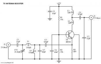
This is a straightforward circuit for a UHF band TV antenna booster that provides a gain of 15 dB. This low-cost antenna booster is simple and easy to construct. The UHF band TV antenna booster circuit is designed to enhance...
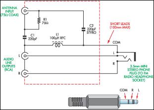
This document presents a concept for a low-cost adapter that enables the connection of a portable FM radio or MP3 player with an FM tuner to an external antenna and audio equipment, such as a hi-fi system or PC...
For long-distance listeners (DX-ers), it is a pleasure to tune into an 8 MHz wide band that is typically unoccupied but can provide periods of clear reception during the Sporadic E season from various distant countries. Usually, only one...
Loop Antennas are considered to be small when their diameter drops below about 1/10 of the wavelength they are intended to be used at. In this case, the term "Tiny" is used because the antenna's diameter is about 1/30,000...
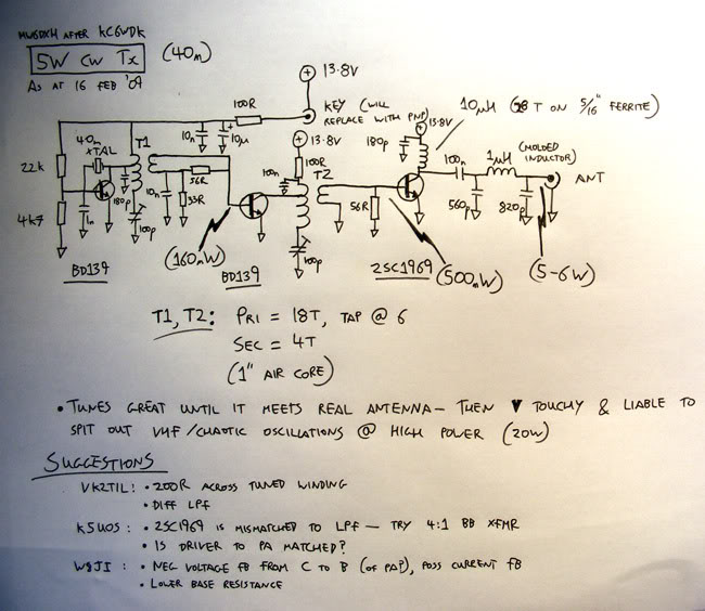
A newly licensed individual is engaging in traditional methods of amateur radio, focusing on continuous wave (CW) communication and homebrewing. They have constructed several basic receivers, an antenna matcher, a standing wave ratio (SWR) meter, a PC-rig interface, and...
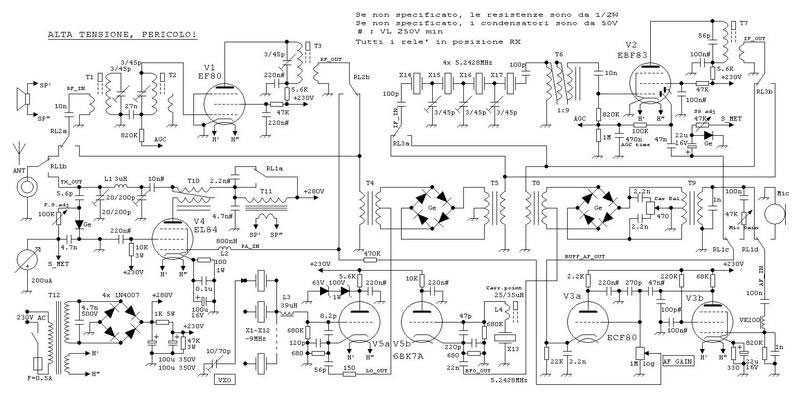
This true SSB transceiver is built around just 5 vacuum tubes, with no transistors nor ICs. Superhet receiver with AGC and S-meter drives a loudspeaker, 5W transmitter, very stable VXO uses CB crystals to cover 20m ham band. A...