
QRP HF LINEAR AMPLIFIER Circuit
The described linear amplifier circuit utilizes two pairs of BC547 transistors in a push-pull configuration, which is effective for achieving linear amplification with minimal distortion. The use of a single diode and resistor for biasing simplifies the biasing arrangement, ensuring that both pairs of transistors operate efficiently. The transformer T1 plays a crucial role in matching the impedance of the driver stage to the low impedance required by the output stage, enhancing overall performance.
The construction technique, referred to as "ugly-bug," allows for a practical approach to prototyping and experimenting without the constraints of conventional PCB layouts. This method is particularly useful in RF applications where space is limited, and components must be arranged in a way that minimizes parasitic effects. The copper-clad board serves as both the substrate for component placement and the ground plane, contributing to the amplifier's performance stability.
Decoupling capacitors (10nF and 33nF) are strategically placed at both ends of the amplifier circuit to filter out high-frequency noise and stabilize the power supply, ensuring that the transistors receive a clean and stable voltage. The careful selection of wire gauge for the transformer windings is critical, as it affects the inductance and the overall efficiency of the transformer. The dual winding configuration of T1 allows for effective energy transfer from the driver stage to the output stage.
Mounting the transistors with their legs in the air enhances cooling and reduces the risk of overheating, which is vital in high-power applications. The compact design of the amplifier, while not visually appealing, demonstrates the effectiveness of the engineering principles applied, resulting in a functional and efficient HF amplifier suitable for various applications in amateur radio and other RF communication systems.This project was a particular surprise for me in that the BC547 (equiv 2N2222) can be used to build a 500mW linear amplifier covering the entire HF band with excellent spectral purity and no neutralizing at all. Ugly-bug construction was used but I dare say that the good results are partly to do with the method of construction.
The circuit is fair ly straight-forward and does not even need any form of RF neutralizing. Two pairs of BC547 transistors are used in a push-pull type of output stage, biased by a single diode and resistor. The driver is also very conventional using T1 to transform the drive impedance to a very low value for the output pairs.
The amplifier is constructed on a piece of copper-clad board 45mm long by 17mm wide. Superglue a 44mm long by 3mm wide strip of copper-clad board along the center. This will become the battery supply rail. Using a sharp knife, remove some copper to form a 3mm x 3mm pad at one end of the battery rail to form the RF output terminal. Next fit the 10n and 33n is decoupling capacitors; one pair at either end. These should lay flat on the board. The rest is easy after you see the photographs. T1 primary is 14-turns of very thin wire (0. 1mm Dia. ) and the secondary is 1+1 turn of thin wire (0. 2mm Dia. ). T1 former is two of the smallest ferrite beads I could find. You can just see it in the left-hand photograph above. T1 is composed of two grey ferrite beads. The right-hand photograph shows T2 and the mounting of the two output pairs of BC547 transistors. T2 is a little special. I found two small ferrite rings in the junk-box and decided to give them a try. The windings are 11-turns three flar wound using thin wire (0. 2mm Dia. ): The five transistors are all mounted on their heads using super-glue and with their legs in the air spread wide apart.
The finished linear amplifier does not look very pretty but it is very small. It is less than 10mm high and looks like this. Here you can see it beside my parker pen for comparison (I thought it would be better than a common 1-crown coin). 🔗 External reference
Related Circuits
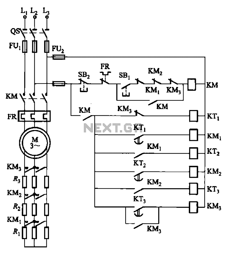
The circuit depicted in Figure 3-159 employs complementary operation three times along with three relay contacts. This is followed by the automatic elimination of the rotor circuit resistance levels, ultimately reducing the rotor winding variable resistor to zero (fully...

A flashing LED indicates the need to water a plant in a 3V powered circuit. This circuit is designed to signal when a plant requires water. A LED flashes at a specified interval. This circuit operates on a 3V power...

The TS4962 is a differential class-D BTL power amplifier capable of driving up to 2.2W into a 4-ohm load and 1.4W into an 8-ohm load at 5V. It achieves outstanding efficiency (typical 88%) compared to standard AB-class audio amplifiers....
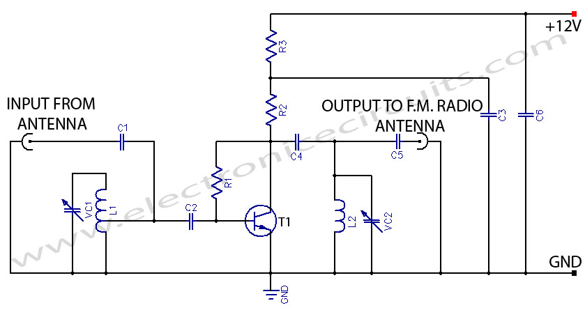
This FM booster allows for clear reception of programs from distant FM stations. The circuit features a common-emitter tuned RF preamplifier utilizing the VHF/UHF transistor 2SC2570 (only labeled as C2570 on the transistor body). The input coil L1 is...
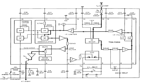
The TDA7000 is an integrated circuit (IC) designed for FM portable radios, featuring a Frequency-Locked Loop (FLL) system with an intermediate frequency of 70 kHz. It incorporates several functions, including an RF input stage, mixer, local oscillator, IF demodulator,...
Environmental interference can affect the transfer switching, leading to the production of burrs in confidence disgrace. The switch position signal will control the computer system with the reliability of lanthanum burrs. The work has some impact. Glitches are typically...