
Plant Watering Watcher Circuit Schematic

This circuit operates on a 3V power supply, which can be provided by two AA batteries in series or a similar voltage source. The core of the circuit includes a microcontroller or a simple timer IC, such as the 555 timer, configured in astable mode to generate a square wave output. This output drives a light-emitting diode (LED), which flashes at regular intervals to alert the user that the plant requires watering.
The circuit can be enhanced by incorporating a soil moisture sensor. This sensor monitors the moisture level in the soil and provides feedback to the microcontroller. When the moisture level falls below a predefined threshold, the microcontroller activates the LED, causing it to flash. This feedback loop ensures that the LED only signals when the plant truly needs water, thereby conserving battery life and preventing over-watering.
A resistor in series with the LED limits the current to prevent damage to the LED. Additionally, a capacitor may be used in conjunction with the timer IC to set the flashing frequency of the LED. The values of the resistor and capacitor can be adjusted to customize the flashing rate according to user preferences.
For added functionality, a buzzer or an additional alert mechanism can be integrated into the circuit. This would provide an audible signal in conjunction with the visual LED indication, making it easier for the user to recognize when the plant needs water, especially from a distance.
Overall, this circuit is a practical solution for plant care, combining simple electronics with effective monitoring to support healthy plant growth.A flashing LED signals the necessity to water a plant, 3V powered circuit This circuit is intended to signal when a plant needs water. A LED flashes at a.. 🔗 External reference
Related Circuits
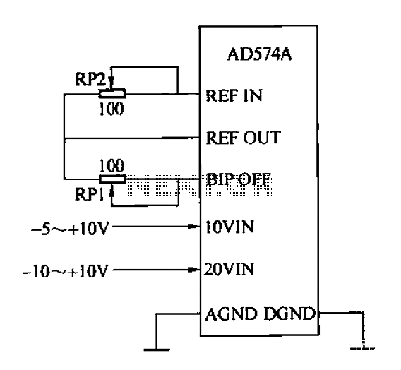
The AD574A is a high-performance 12-bit successive approximation analog-to-digital (A/D) converter that can interface directly with an 8 or 16-bit microprocessor bus. The input to the AD574A can be either unipolar or bipolar. The unipolar analog input voltage range...
The antenna tuning circuit can accommodate 1/2 wave length antennas or higher, for input resistances of 50 Ohms which make it suitable for CB (Citizen Band) transceivers. C1 is for fine tuning and C2 is just for tuning. Turning...
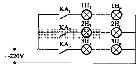
The relay control system utilizes multiple pairs of contacts, allowing for the connection of higher power lamps in parallel. The circuit design is straightforward; by altering the capacitance of the capacitor, different flashing frequencies can be achieved. The described circuit...
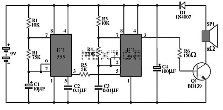
The circuit utilizes IC1 to create an astable multivibrator configuration. It is designed to generate a low-frequency output of approximately 1 Hz at pin 3, which is determined by the resistor values R1, R2 and capacitor C1. The output...
The amplifier drives a pair of speakers using two LM3876 amplifier chip circuits (50 watts per channel) or a pair of headphones with Meier Crossfeed through a clarifier and a dual OPA2134 Opamp. It features four selectable band inputs...

The first schematic examined is the base schematic of the transmitter without any modifications. The RC car's transmitter circuit consists of two halves. One side (on the left) is predominantly digital. When a switch (1-4) is pressed, IC1 becomes...
Warning: include(partials/cookie-banner.php): Failed to open stream: Permission denied in /var/www/html/nextgr/view-circuit.php on line 713
Warning: include(): Failed opening 'partials/cookie-banner.php' for inclusion (include_path='.:/usr/share/php') in /var/www/html/nextgr/view-circuit.php on line 713