
Quad Power Supply For Hybrid Amplifier
This power supply circuit comprises several key components and configurations that ensure optimal performance and efficiency. The LT1074CT serves as a highly efficient voltage regulator, allowing for a compact design while minimizing power losses. The use of a cascade generator for the high voltage output is particularly advantageous, as it enables the generation of the necessary 170 V for the SRPP stage without the need for bulky transformers or additional components. The bridge rectifier, utilizing Schottky diodes, provides a low forward voltage drop, enhancing overall efficiency.
In terms of thermal management, careful consideration has been given to the placement of heatsinks for both the 12 V regulator and the LT1074CT. Ensuring adequate cooling is crucial, especially when operating close to the component's maximum ratings. The inclusion of diode D7 for voltage adjustment demonstrates a thoughtful design approach, allowing for flexibility in output voltage requirements.
The choice of transformers and chokes is critical in maintaining the integrity of the power supply. Standard components have been selected to ensure availability and ease of assembly, while the option to add additional filtering stages can further enhance performance by reducing high-frequency noise that could affect circuit operation.
Overall, this power supply design is robust and versatile, suitable for a variety of applications beyond the Simple hybrid amplifier, and exemplifies best practices in electronic design by leveraging standard components, efficient voltage regulation, and effective thermal management strategies.This power supply was designed for use with the Simple hybrid amp` published elsewhere in this issue. It is of course suitable for use in other applications as well. We`ve used a cascade generator for the 170 V, a switch mode supply for the 16 V, a series regulator for the 12 V and a separate transformer for the 6.
3 V filament supply. We`ve chosen an LT1074CT (IC1) for the regulator, which means that the circuit can be built with relatively standard components and will have a high efficiency. The power loss is less with this device compared to a linear voltage regulator. This allows us to use a higher transformer voltage and a smaller cascade section to generate the 170 V (which is required for the SRPP stage in the amplifier).
The lower input current also results in smaller losses in the bridge rectifier (D1 to D4). A standard 12 V regulator (IC2) turns the 16 V into a stabilised voltage for the buffer stage. When an ECC83 (12AX7) is used in the hybrid amp we could use this 12 V to power the filaments in the valve as well, although we really need 12. 6 V. The current taken by the valve is about 150 mA, which means that the 12 V regulator needs to be fitted with a heatsink.
This can be a small version of an SK129 heatsink from Fischer (38. 1 mm, 6. 5 K/W). To increase the voltage by 0. 6 V we`ve added diode D7 to the ground connection of the regulator. If an output voltage of 12 V is required you should close JP1, which shorts D7. IC1 and D5 require a little more cooling and for this the 63. 5 mm version of the SK129 will suffice (4. 5 K/W). Both components can be mounted on opposite sides of the heatsink. You have to make sure that they are electrically isolated from each other and the heatsink! You should take a look at the website of Linear Technology ( and take note of the layout recommendations regarding the use of an LT1074. You can use standard chokes for L1 and L2, rated at 5 A. If you want to remove more of the residual 100 kHz switching frequency you could always add an extra LC filter at the output.
The diodes in the bridge rectifier are B10100`s. These are Schottky rectifiers, which have a low forward voltage drop (only 0. 7 to 0. 8 V at 10 A). We have chosen diodes with a reverse voltage rating of 100 V so we have the option of using an LT1074HVCT instead. This can work with an input voltage of up to 60 V, which means we could use a 40 VAC transformer. The same cascade circuit can then easily generate 220 VDC. The standard LT1074CT can cope with up to 45 V, so we`re using IC1 fairly close to the limits of its specifications in this circuit.
A cascade circuit generates the HT supply for the valve. It would also have been possible to use a separate transformer with a bridge rectifier and smoothing capacitor to generate this voltage. But then we`d have to find a 4. 5 VA transformer with a 40 V secondary and connect it the wrong` way round. As this isn`t exactly a standard transformer we dropped that idea. The source for the cascade generator is now an 80 VA transformer. The capacitors in the cascade circuit have higher values than are strictly necessary. This makes it easier to calculate the expected output voltage. In our case this is 4 x 30 x v2V for the no-load voltage, which comes to nearly 170 V. L3 and C22 filter out any HF interference coming from IC1. When the cascade supplied 20 mA the output voltage dropped to 140 V. At heavier loads we recommend that you use a smaller cascade circuit and a higher transformer voltage (and also use an LT1074HVCT because of the higher input voltage).
The filament voltage for the valve is generated by a 4. 5 VA transformer, which in practice had an output a bit above 6 V and therefore came closer to the required 6. 3 V. Another solution is to use a special transformer or a stabilised 6. 3VDC supply. Any of these will work, so it`s down to your own preference which of these you`ll use. It is in principle possible to use the supply for two channels. However, if you use the ECC88 in the amplifier you may find it`s necessary to use a separate cascade generator for each channel.
🔗 External reference
Related Circuits
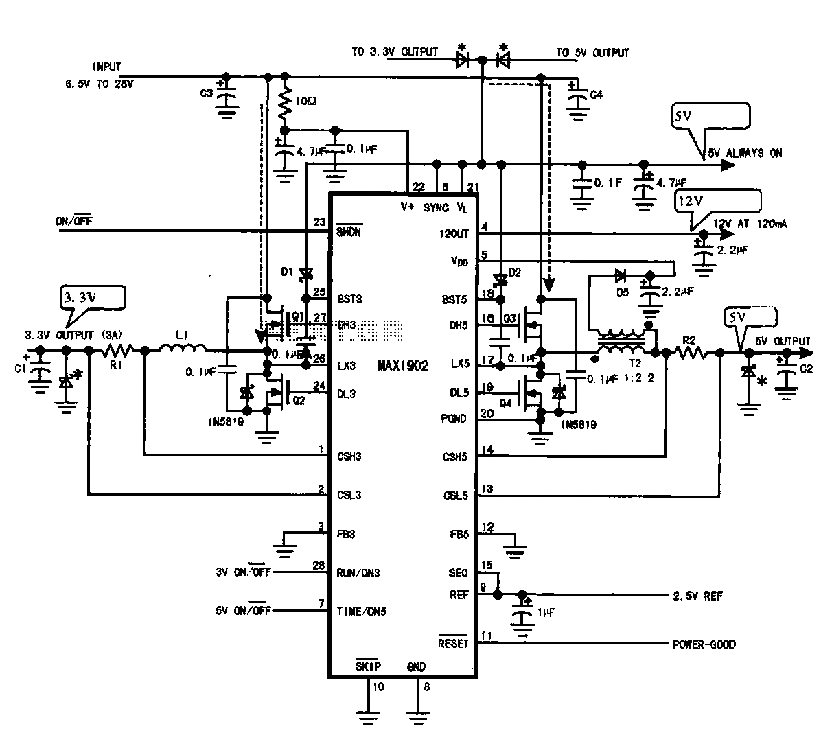
Multi-output power supply circuit (MAX1902). This circuit illustrates the power supply configuration for a notebook computer motherboard, utilizing the MAX1902 chip for power control. It is designed to convert the battery's DC voltage into multiple DC voltage outputs. The multi-output...
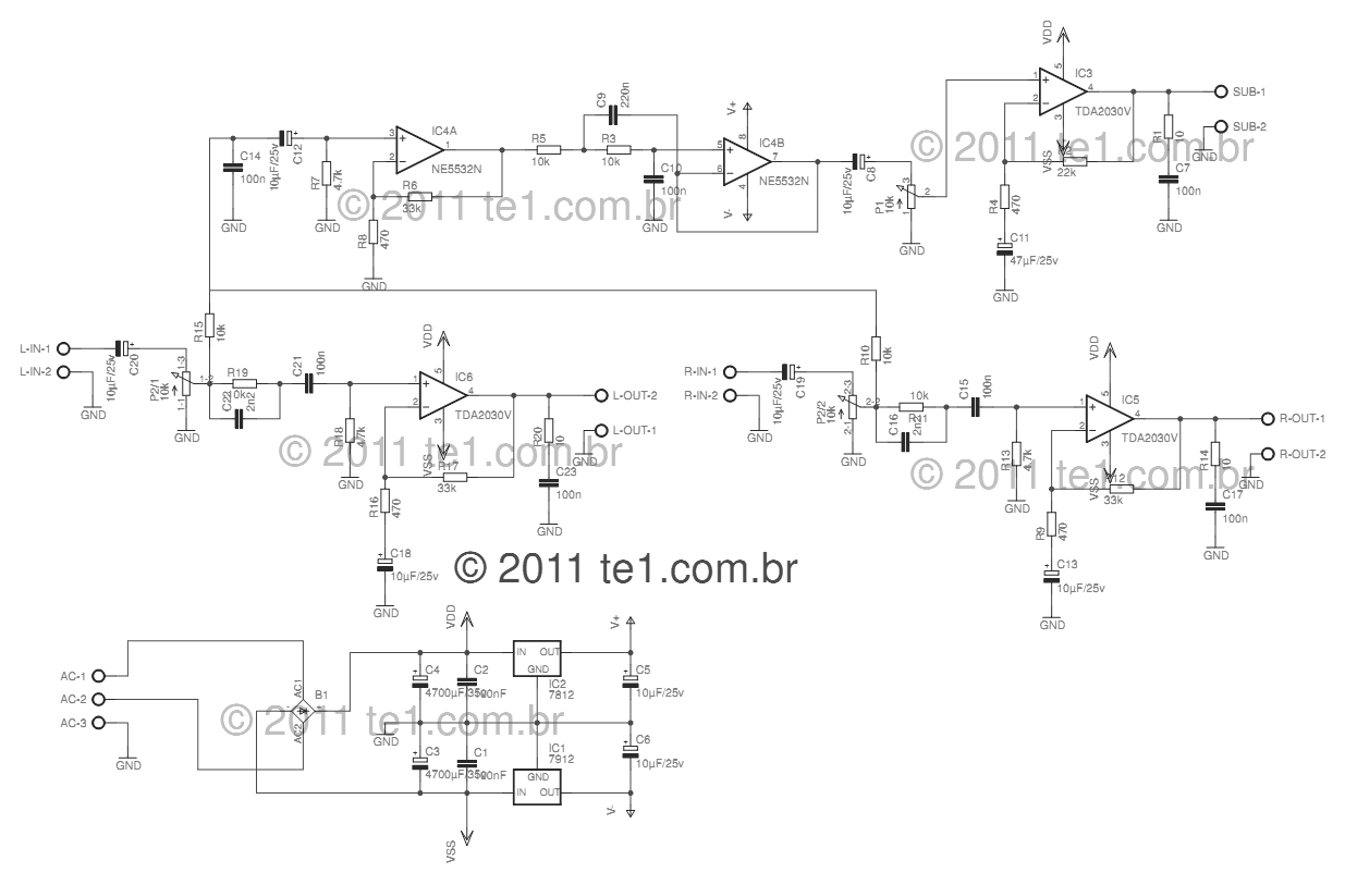
This circuit is a complete application for a 2.1 amplifier system, featuring two satellite speakers for TDA and one subwoofer. It is commonly used in commercial applications to enhance the audio output of computers using a stereo amplifier along...
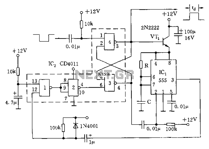
The circuit consists of four 2-input NAND gates and a CMOS CD4011 type 555 timer, allowing for either a static or high-time period output while maintaining minimal power consumption. Additionally, the circuit features a 3-door and 4-door composition RS...
This simple audio power amplifier was originally designed for a circuit board workshop, conducted by the OSU IEEE Student Group. At the workshop, 20 participants each constructed this amplifier, by etching and drilling the single sided circuit board, soldering...
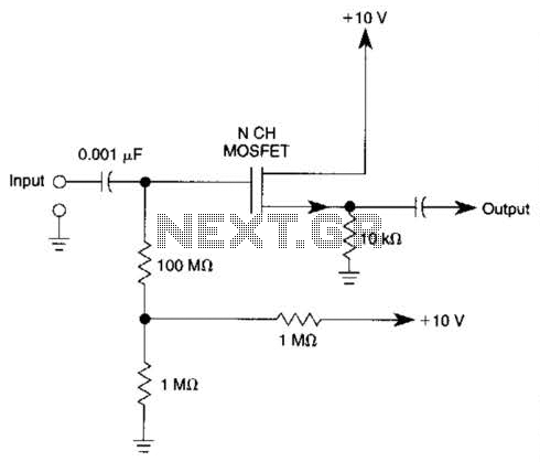
Biasing methods for an N-channel MOSFET to form a unity-gain noninverting amplifier or source-follower. The N-channel MOSFET can be utilized in various configurations, with one common application being the unity-gain noninverting amplifier, also known as a source-follower. In this configuration,...
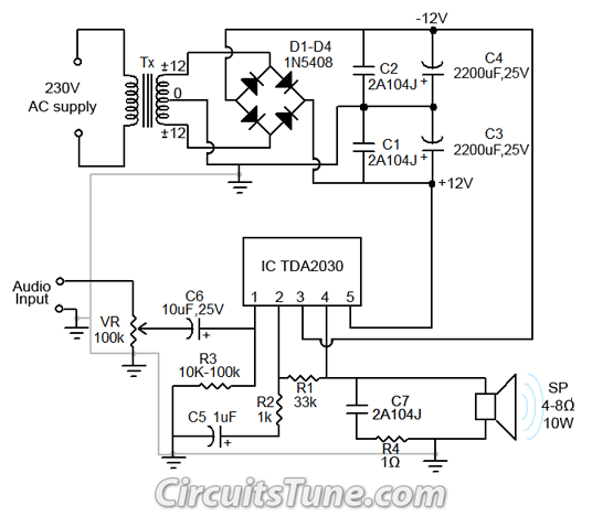
All ground points in the circuit should be connected to a single point and grounded if possible, or connected to the transformer's 0V marked wire as shown in the circuit. In electronic circuit design, proper grounding is crucial for maintaining...
Warning: include(partials/cookie-banner.php): Failed to open stream: Permission denied in /var/www/html/nextgr/view-circuit.php on line 713
Warning: include(): Failed opening 'partials/cookie-banner.php' for inclusion (include_path='.:/usr/share/php') in /var/www/html/nextgr/view-circuit.php on line 713