
Quartz Crystal Windup Wall Clock
The clock movement is made in Korea by "Sau Jin LTD" "Dae Woo CO LTD" and has no jewels. It measures 4.5 inches in diameter by 1.5 inches deep plus 1.5 inches for the hands and drive wheel shafts, so the clock face and hands are about 3 inches from the wall. The pendulum period is close to 53.4 complete swings per minute. Can't figure out why that particular period was used. I have seen similar movements on eBay.
The clock pendulum was made using a 10 inch, 3/16" wooden dowel with a strong magnet attached to the bottom and a small weight near the top to adjust the period close to 53 beats per minute. The circuit board and electromagnet to drive the pendulum are located on a small shelf (not shown) and positioned so the pendulum magnet swings close to the stationary electromagnet and receives a small pulse on each swing to sustain oscillation. The pulse duration is about 5% of the pendulum period, and an LED is used to indicate the pulse output. The clock starts fairly easily by releasing the pendulum near the magnet when the LED flash is observed.
Quartz Crystal Synchronizing Circuit:
The synchronizing circuit that produces a short magnetic pulse to keep the pendulum in near perfect time was made using a crystal oscillator and binary counters to generate a 60mS pulse at the required rate of 53.4241 PPM. The exact rate was not known but appeared to be close to 53.5 cycles per minute by adjusting the pendulum length and monitoring the error over a several-hour period. The oscillator circuit uses an old 20KHz quartz crystal, but other low-frequency crystals can be used. A standard watch crystal of 32.768 KHz is probably the best and easy to obtain. The idea is to allow the counters to count to the desired number and then reset the counters, generate the desired pulse, and repeat the cycle. In this case, a time of 60/53.4241, or 1.1231 seconds, was needed. At a frequency of 20KHz, this corresponds to about 20000 * 1.1231 or 22462. To detect this number, a multiple input NAND gate (CD4068) is used with inputs connected to the appropriate counter stages. Each counter stage has a value of twice the one before (divide by 2), so the values are 1, 2, 4, 8, 16, 32, and so forth. The selected counter stages that add up to 22462 are:
- Stage 3 (Q3, pin 6) of the second counter with a value of 16384
- Stage 1 (Q1, pin 9) of the second counter with a value of 4096
- Stage 11 (Q11, pin 15) of the first counter with a value of 1024
- Stage 10 (Q10, pin 14) of the first counter with a value of 512
- Stage 9 (Q9, pin 12) of the first counter with a value of 256
- Stage 8 (Q8, pin 13) of the first counter with a value of 128
- Stage 7 (Q7, pin 4) of the first counter with a value of 64
Total = 22464
The error is about 2 counts out of 20,000 or approximately 4 seconds per day. Further adjustment can be made by fine-tuning the oscillator frequency by adjusting the value of the 1000pF capacitor at pin 1 of the inverter.
The overall design of the circuit includes a power supply suitable for the oscillator and counter ICs, typically a regulated 5V supply, which can be derived from a standard wall adapter or battery source. The oscillator circuit should be configured to ensure stability and low drift, which is critical for timekeeping applications. The output from the oscillator feeds into the binary counters, which are configured in a cascading manner to achieve the necessary division ratio. The NAND gate is employed to combine the outputs from the selected counter stages to generate the precise pulse required to drive the electromagnet, ensuring that the pendulum is kept in motion with minimal deviation from the desired timing.
The electromagnet's placement and the pendulum's magnet must be optimized for effective coupling, ensuring that the magnetic pulse is strong enough to sustain the pendulum's motion without causing excessive damping. The clock's mechanical components should also be inspected and maintained to prevent any mechanical errors from affecting the timekeeping accuracy.Last year, I found a 31 day pendulum wall clock (dissambled) in a box of parts at a swap meet and decided to try and put it together and regulate it with a quartz crystal oscillator. The escapement part that rocks back and forth and drives the pendulum was missing and had to be made from a couple razor blade pieces and heavy copper wire.
The razor blade escapement worked well but only allowed the movement to advance as the pendulum swung, and would not sustain the pendulum motion by itself. But this wasn't a problem since the quartz crystal divider circuit provides energy to the pendulum with an electromagnet to keep it swinging with only a 5 second error per day.
The 31 day mainspring was included, but I wanted to use a weight and drive wheel in place of the spring. The clock movement is made in Korea by "Sau Jin LTD" "Dae Woo CO LTD" and has no jewels. It measures 4.5 inches diameter by 1.5 inches deep plus 1.5 inches for the hands and drive wheel shafts, so the clock face and hands are about 3 inches from the wall.
The pendulum period is close to 53.4 complete swings per minute. Can't figure out why that particular period was used. I have seen similar movements on ebay. The clock pendulum was made using a 10 inch, 3/16" wooden dowel with a strong magnet attached to the bottom and a small weight near the top to adjust the period close to 53 beats per minute. The circuit board and electromagnet to drive the pendulum are located on a small shelf (not shown) and positioned so the pendulum magnet swings close to the stationary electromagnet and receives a small pulse on each swing to sustain oscillation.
The pulse duration is about 5% of the pendulum period and a LED is used to indicate the pulse output. The clock starts fairly easily by releasing the pendulum near the magnet when the LED flash is observed.
Quartz Crystal Synchronizing Circuit: The synchronizing circuit that produces a short magnetic pulse to keep the pendulum in near perfect time was made using a crystal oscillator and binary counters to generate a 60mS pulse at the required rate of 53.4241 PPM. I didn't know the exact rate, but it appeared to be close to 53.5 cycles per minute by just adjusting the pendulum length and monitoring the error over a several hour period.
The oscillator circuit uses an old 20KHz quartz crystal, but other low frequency crystals can be used. A standard watch crystal of 32.768 KHz is probably the best and easy to obtain. The idea is allow the counters to count to the desired number and then reset the counters, generate the desired pulse, and repeat the cycle.
In this case, I needed a time of 60/53.4241, or 1.1231 seconds. At a frequency of 20KHz, this is about 20000 * 1.1231 or 22462. To detect this number, a multiple input NAND gate (CD4068) is used with inputs connected to the appropriate counter stages. Each counter stage has a value of twice the one before (divide by 2), so the values are 1,2,4,8,16,32 and so forth.
So the problem was to select the counter stages that add up to 22462, which works out to: Stage 3 (Q3, pin 6) of the second counter with a value of 16384 Stage 1 (Q1, pin 9) of the second counter with a value of 4096 Stage 11 (Q11, pin 15) of the first counter with a value of 1024 Stage 10 (Q10, pin 14) of the first counter with a value of 512 Stage 9 (Q9, pin 12) of the first counter with a value of 256 Stage 8 (Q8, pin 13) of the first counter with a value of 128 Stage 7 (Q7, pin 4) of the first counter with a value of 64 Total = 22464 So, the error is about 2 counts out of 20,000 or maybe 4 seconds per day. Further adjustment can be made by fine tuning the oscillator frequency by adjusting the value of the 1000pF cap at pin 1 of the inverter.
🔗 External reference
Related Circuits
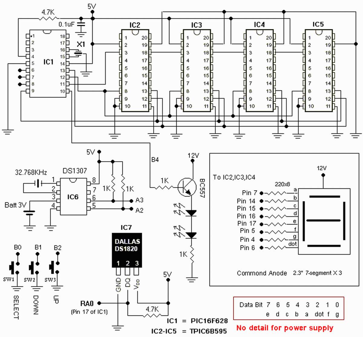
The clock is based on the PIC16F877 microcontroller from Microchip Technology Inc., which performs all of the logic necessary to decode the MSF signal and display the time on twelve 7-segment displays. The circuit design incorporates the PIC16F877 microcontroller, a...
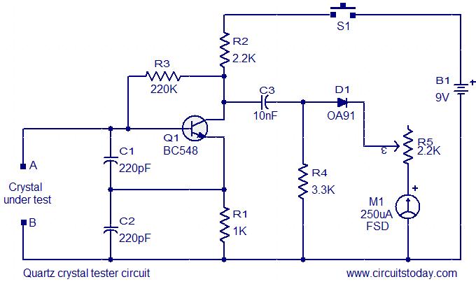
This is a straightforward and cost-effective circuit designed for testing quartz crystals. A Colpitts oscillator is employed using transistor T1. When the crystal is connected between terminals A and B, the circuit generates high-frequency oscillations. These oscillations will only...

The FM transmitter is relatively simple to build and requires only one adjustment, making it ideal for beginners. It is important to clarify that, with wide-band deviation, the Voltage Controlled Oscillator (VCO) is never locked in phase, only in...
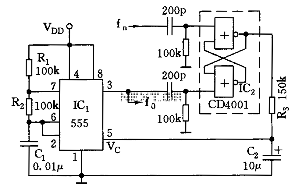
The circuit illustrated consists of a 555 timer along with resistors R1 and R2, and capacitor C1, forming a composition-controlled multivibrator. The oscillation frequency is influenced not only by the RC time constant but also by the adjustment of...
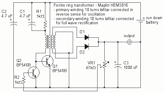
How to create a Joule Thief circuit to power a clock, including circuit details and tips for construction. The Joule Thief circuit is a simple and efficient boost converter that allows the extraction of usable voltage from low-voltage sources, such...
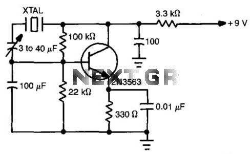
This simple circuit will oscillate with a wide range of crystals. Connect several different types of crystal holders in parallel to improve versatility. The 3 to 40 pF capacitor adjusts crystal frequency over a small range for setting to...