
Crystal Controlled FM Transmitter

The FM transmitter circuit is a practical application of phase-locked loop technology, integrating essential components to facilitate frequency modulation for broadcasting purposes. The VCO is the heart of the transmitter, allowing frequency adjustment based on the control voltage derived from the loop filter. The use of a Varicap diode for modulation introduces an efficient method of varying the oscillator frequency, which is critical for FM transmission.
The inclusion of a frequency divider enhances the circuit's flexibility, enabling the use of a higher frequency VCO while producing a lower frequency output suitable for the crystal oscillator. This technique is common in synthesizer designs, where the goal is to maintain lock between the VCO and the reference frequency while allowing for modulation.
The filtering stage before the VCO is crucial for maintaining signal integrity and stability. The choice of components, such as the BC547 transistors, reflects a focus on ensuring that the modulation does not disrupt the locking mechanism of the PLL. The isolation of the VCO from the antenna through an additional transistor further enhances the reliability of the circuit, preventing unintended frequency shifts caused by external influences.
The design's robustness is evident in the over-engineering approach, particularly with the choice of the LM317T voltage regulator, which ensures that the prescaler operates within safe voltage limits. This consideration is essential for maintaining the longevity and functionality of the circuit in various operating conditions.
In summary, the FM transmitter circuit is a well-structured design that balances simplicity and functionality, making it accessible for beginners while also providing the necessary features for effective FM broadcasting. The careful selection of components and circuit topology demonstrates a thorough understanding of synthesizer principles and frequency modulation techniques.The FM transmitter is relatively simple to build and with only one adjustment it is ideal for the absolute beginner. But before I continue, let me just make one thing clear. With Wide-Band deviation, the VCO is never locked in phase, only in frequency. It uses a Varicap diode to modulate an oscillator, then lock the oscillator in a Phase Locked Lo op, and compare it to a crystal oscillator. The circuit follows that of a simple textbook synthesiser comprising a Voltage Controlled Oscillator (VCO), a damped Loop Filter, a Reference Oscillator (Crystal) and a Frequency Comparator. The only difference is that I have added a frequency divider chip to divide the VCO frequency by 64. This means that if the VCO operates at 100MHz, the output from the divider will be 1. 5625MHz. If the crystal oscillator is also 1. 5625MHz then the loop will be "in-lock. " The control voltage from the filter to the VCO steers the frequency of the VCO so that the output of the divider is ALWAYS 1.
5625MHz. Any deviation from this will result in a change of the loop voltage to move the VCO back to 100MHz. I will not delve too deeply into the in`s and out`s of synthesisers. I have already written several pages of information about them and the stages that are needed to make a working synthesiser. The specific circuit is shown above. The "Prescaler" (divider) chip needs to have a supply voltage of only 5v (+/- 0. 25v) so the LM317 has been included. I used the LM317T due to it`s larger can size (and I have got a lot of them) so it will tolerate a supply voltage of greater than 13.
8vDC without burning. All has been somewhat over-engineered. IC1 (CD4001) is the crystal oscillator with an extra gate used as nothing more than a buffer stage. This feeds the frequency comparator of a CD4046 (IC2). The comparator output is filtered with a "slack- handfull" of resistors and caps to feed the VCO; a BC547. A second BC547 has been used to isolate the VCO from the antenna. Without this device the loop would have the tendency to jump out of lock if you touched the antenna. The VCO is also coupled to the divider, IC3, which can be any one of a selection of chips. MB501, SA701, SP8704 and CA12022 are all the same device. The filter time-constant is a couple of second or so. This makes it take about one second for the loop to stabilise. If this were not the case then the modulating frequency would be seen as a frequency error and the loop would correct the error (remove the modulation).
The modulation input is via a 100K resistor and 3n3 capacitor which provides the little pre-emphasis needed for an FM broadcast transmitter. If your AF input comes from a stereo encoder then remove the 3n3 since the pre-emphasis must occur BEFORE encoding.
I hope to post a stereo encoder soon, but I give no promisses. If you are one of those who likes to dissmantle circuits, then you may notice that I have used the CD4046 Signal and Reference the wrong way around - I have used the signal input for the Reference frequency and the Reference input for the signal frequency. This is because the Reference input is designed to be fed from an external source and so it will respond to small small signals (ca: 200mV) whereas the Signal input is designed to be fed from the CD4046s own CMOS logic level oscillator.
IC3 is an ECL device with only 1v output signal and is therefore NOT CMOS compatible. The result of this is that the output sense of the frequency comparator is reversed! That is why the Varicap Diode (BB105) is reference to +5v and Not to Ground. 🔗 External reference
Related Circuits
An oscillator is an amplifier with a feedback loop from output to input. The Barkhausen criteria state that for oscillation to occur, the product of the gains around a loop must be equal to or greater than unity, and...

The schematic for this project is deceptively simple compared to the complexity of the circuit's operation. The two signals generated are mixed together at the base of transistor T2, and once it exits the collector of the transistor, the...
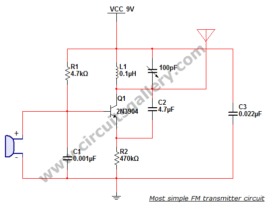
This is the simplest single transistor FM wireless transmitter circuit ever posted in CircuitsGallery. In the field of telecommunications, frequency modulation (FM) transmits information by altering the frequency of a carrier wave based on the message signal. FM utilizes...
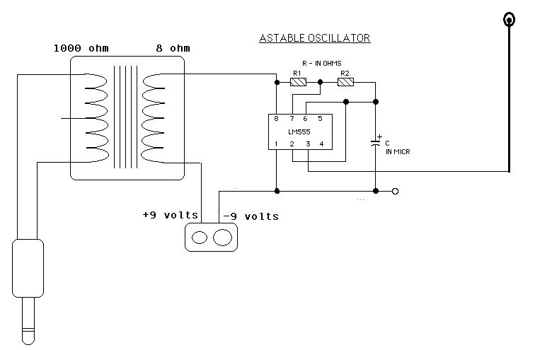
Two ICM7555 CMOS 555 timers are available, and there is an inquiry about effective AM radio transmitter circuits that utilize one or both of these timers. The ICM7555 is a low-power CMOS version of the classic 555 timer, which can...
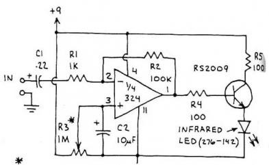
FM transmitter IC manufacturers and suppliers include FM transmitter IC manufacturers with Bluetooth capabilities. The FM transmitter features an integrated circuit with four channels. The TNA029 IR audio transmitter IC is a low-cost solution with high performance. The FM transmitter...
This is a Voltage Controlled Oscillator (VCO) circuit. This circuit is based on a Hartley oscillator. The frequency depends on the values of C1 and L1. The Voltage Controlled Oscillator (VCO) circuit described operates using a Hartley oscillator configuration, which...
Warning: include(partials/cookie-banner.php): Failed to open stream: Permission denied in /var/www/html/nextgr/view-circuit.php on line 713
Warning: include(): Failed opening 'partials/cookie-banner.php' for inclusion (include_path='.:/usr/share/php') in /var/www/html/nextgr/view-circuit.php on line 713