
question about ceramic resonator
In radio frequency (RF) design, the use of resonators and filters is critical for achieving desired selectivity and performance in receivers. The resonator's harmonic response can significantly affect the overall performance of the system, particularly in applications involving single conversion receivers. The 455 kHz IF is commonly used due to its balance between performance and the challenges posed by higher RF frequencies.
In practice, employing a ceramic resonator as a first IF filter can be advantageous in certain applications, but it may not always yield optimal results. The sensitivity of ceramic filters to harmonics necessitates careful consideration of their placement within the signal chain. While they can be effective in second IF stages, their reliability as the sole filter in a single conversion system may be questionable.
To enhance performance, cascading filters can improve selectivity, but this approach must be implemented with care to avoid input/output isolation issues. The recommendation to buffer the output between cascaded filters is prudent, as it ensures that the characteristics of each filter stage are preserved and that signal integrity is maintained.
For further evaluation, constructing a standalone filter evaluation board can provide valuable insights into the resonator's performance under controlled conditions. By testing with known input/output impedances and drive levels, the characteristics of the ceramic resonator can be thoroughly assessed, facilitating informed decisions regarding its application in receiver design.
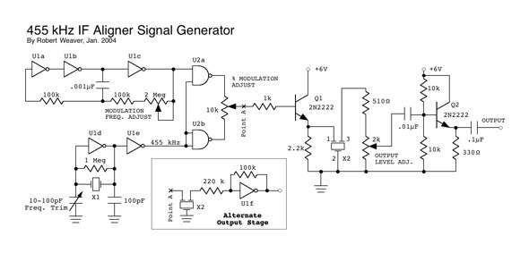
Ultimately, the choice of filters and resonators in RF applications should be guided by the specific requirements of the design, including considerations for frequency response, harmonic rejection, and overall system performance.It looks as if they are highly prone to harmonics meaning in this case, that if the resonator is 455KHz, it will also allow 910Hz and 1820KHz and 3. 640MHz which seems to be dominant and on up. But the frequency around 3MHz seems to be prevalent and one or two multiple of that. It first I thought I was getting intermod so I changed my mixer to a double balanced passive mixer and reduced the gain of the front end. I see now why certain frequencies reoccur. It is not intermod it is the harmonics. So my question is this. Is it common practice or taboo to use a ceramic resonator as a 1st IF filter Maybe there are better ones then the cheap one I bought but I am very dissatisfied with it`s performance since my intention was to use it in a single conversion receiver design. In fact I even used two of them. One after the post mixer amp then a single stage amplifier followed by another. It helped but I still had the same harmonic responses. The use of 455 kHz I. F. depends on the RF frequency. Usually you want RF to IF ratio of 5 to 7. Too high RF will require too much RF filtering to reduce mixer image. Too high an I. F. will be subject to A-B (Able-Baker) spurs. Most new receivers are direct conversion. The mixer is very precise to avoid D. C. offsets and 2nd order crossmodulation. There is usually a automated self calibration within the direct conversion I. C. The use of 455 kHz I. F. depends on the RF frequency. Usually you want RF to IF ratio of 5 to 7. Too high RF will require too much RF filtering to reduce mixer image. Too high an I. F. will be subject to A-B (Able-Baker) spurs. Most new receivers are direct conversion. The mixer is very precise to avoid D. C. offsets and 2nd order crossmodulation. There is usually a automated self calibration within the direct conversion I. C. edit edit* Is this with PLL systems only If I follow this correctly, you are talking about the output level of the VFO or VCO It makes sense.
I have noticed that re-tapping the coil will change the performance to a degree but I still think the ceramic filter is more sensitive to harmonics and that it could be cured through a crystal filter. So if this is PLL only, than what would be the cure in a low end VFO type receiver Maybe your over driving the filter input causing input/output isolation issues.
I would not go over 0 dBm at the filter. You can cascade the filters for better selectivity but the murata data sheets suggest that you put a buffer in between. acquiring knowledge is like doing a jig saw puzzle, many of the bits on their own dont make sense, but they are all needed to give a complete picture.
"Eric Gibbs" Maybe your over driving the filter input causing input/output isolation issues. I would not go over 0 dBm at the filter. You can cascade the filters for better selectivity but the murata data sheets suggest that you put a buffer in between. I got the output buffered. I just don`t know if it is common practice to use one of these ceramic filters for a single conversion where it is the only IF filter.
It just seems kind of unreliable. I see them all the time in 2nd IFs and it would be useful for that but the real question is using that as the whole receiver`s selectivity. You now what I`m saying Looking at the internet I have not been able to pull up any schematics where a 455KHz ceramic resonator was the only filter.
Maybe you can build a stand alone filter eval board and test it`s characteristics with known in/out impedance and drive levels. I am sure you have a sig gen you can use no By testing it in stand alone you will get an idea of how it will perform in a circuit.
When I worked in a RF lab we always 🔗 External reference
Related Circuits

The MS6712 is a digital control audio processor designed for low voltage operation, featuring 4 stereo inputs and 4-channel outputs. It integrates volume control, tone adjustment (including bass and treble), balance control (left/right), and fader control (front/rear) within a...
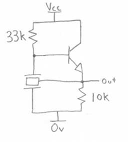
A ceramic resonator can be utilized to construct an oscillator. A single digital inverter can be employed to create a Pierce oscillator. To design a Pierce oscillator using a ceramic resonator and a digital inverter, the following components and configurations...
A newcomer to electronics has questions regarding the interpretation of circuit diagrams. There is uncertainty about the arrangement of wires in these diagrams. Understanding circuit diagrams is essential for anyone involved in electronics, as they serve as a visual representation...
A field effect transistor amplifier features a fixed bias input source with feedback, resulting in very high input impedance and low capacitance. It drives a field effect transistor or emitter follower, despite having a very low output impedance, utilizing...
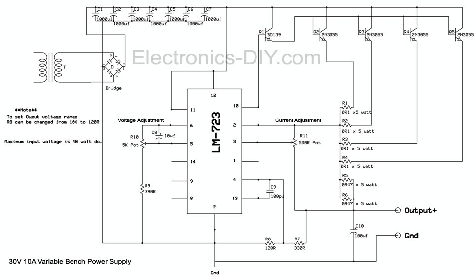
The LM723 current sense and current limit pins (2 and 3) detect a voltage generated by low-resistance current-limiting resistors. When this voltage reaches a specific threshold, the integrated circuit (IC) either shuts down or restricts the power supply output....
The feedback resistor sets the bias of the oscillation circuit. Typically, CMOS ICs utilize feedback resistances ranging from 100k ohms to 10M ohms (commonly 1M ohms), while TTL ICs employ feedback resistances from 1k ohms to 10k ohms (usually...