
quick electronics designs
Additionally, the design repurposes an old LCD alarm clock, although it is likely compatible with LED types as well. It serves various functions, such as watering plants or precisely controlling heating, garden lights, or a Christmas tree. The circuit operates simply: the activating signal is taken in parallel from the original buzzer (which can be removed). When the alarm activates, the set/reset flip-flop is set. The output of the flip-flop is connected to the reset input via a delay network consisting of a 10 MΩ resistor and a 1000 µF capacitor. This configuration allows the flip-flop to reset itself after a delay of approximately three hours, making it ready for a new activation cycle. The delay can be adjusted to any desired length, from seconds to hours, by modifying the resistor and/or capacitor values.
Replacing the LED with an optocoupler enables monitoring of appliance or industrial equipment operation via a PC's serial or parallel port, with the output providing a square wave at mains frequency. The amperometric transformer (TA) used in the prototype is a 200:1, 5A maximum toroidal transformer, originally intended for current measurement. The primary winding (black wire on the left) originally had 2 turns, but a new winding with 4 turns was added to enhance sensitivity (represented by the white wire on top). In Italy, household mains power is typically limited to 3 kW, and with devices like hairdryers consuming up to 1900W, it is crucial to monitor power usage to avoid tripping the mains circuit breaker.
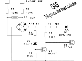
This priority switch circuit is designed to automatically cut power to appliance B when appliance A is powered on, ensuring that appliance A takes precedence and the total power consumption remains within safe limits. A notable feature of this circuit is that it does not require an external power supply and consumes no power when inactive. When current flows through the TA, the LED in the phototriac lights up, triggering the triac to activate the relay that disconnects load B. It is important to note that a zero-crossing optotriac should not be used with this circuit.Snap all connectors on to the flat cable (a small vice will do the job). You get an instant male-male, male-female, female-female serial adaptor, plus a short extender cord. A must-have tool if you`re planning to play with serial ports. You can even put an extra connector for monitoring the RS232 traffic. Another nice tip sent by Randy Rhoade s: did you know that if you connected a null modem between the connectors on one of the ends, the Snake becomes a loop-back tester This circuit has been designed by Gabriele Bandini. His home is full of telephones, modems, and. kids. After a dozen of modem crashes, he decided to put an indicator LED on every phone plug to show to the family when the phone line is free.
If you have a FAX and a phone on the same line, this circuit can show you when to make a phone call without disrupting an incoming fax. If you have an internal modem, this circuit will show you when it is on hook Note that this circuit is designed to work with italian telephones and that you need the written approval of your phone company prior to put something on the phone line.
If you don`t have noticed it yet, I like to reuse hardware objects. This design brings new life to an old lcd alarm clock (but I bet it would work with LED types too). It is useful for a variety of purposes, from watering your flowers to (precisely) switch on the heating, the garden lights or even your christmas tree! The circuit cannot be simpler: the activating signal is picked up in parallel from the original buzzer (that can even be removed).
When the alarm "sounds", the set/reset flip flop is SET. The flip-flop output is also connected to the RESET input, through a 10Mohm x 1000uF delay network. This means that, after the delay time (about three hours on my prototype), the flip-flop resets itself. The daily timer is then ready for a new activation. You can set any delay you like, from seconds to hours, simply adjusting the resistor and/or capacitor values.
Replace the LED with an optocoupler and connect it to the PC serial or parallel port to monitor when an appliance or an industrial equipement is working (the output is a square wave at mains frequency) The amperometric transformer (TA) on my prototype is a 200:1, 5A max. toridal transformer, originally made for current measurement. The primary (black wire on the left) had 2 turns, but I have wound a new one with 4 turns in order to increase sensitivity (it is the white wire on top).
Here in Italy, the amount of mains power for most households is limited to 3 kW. With an hairdryer taking as much power as 1900W, I must check not to exceed the maximum power rating every time I switch on an electric appliance. Failing to do it may result in an unplanned walk out of the home, to restore the mains circuit breaker switch.
I use this priority switch to automatically remove power from appliance B when A is powered on. That is, A takes precedence over B, and the maximum power consumption is never execeeded. One nice feature of this circuit is it does not require an external power supply, and it consumes nothing when not active. When current flows in the TA, the LED in the phototriac lits, and the triac turns on the relay disconnecting load B.
Do NOT use a zero-crossing optotriac with this circuit. 🔗 External reference
Related Circuits

This simple MOSFET power audio amplifier circuit, featuring a TL071C operational amplifier and two MOSFET power amplifiers, can deliver up to 45W at an 8-ohm load. The schematic is based on Siliconix applications and incorporates variations in voltage across...

To eliminate ground loops in the audio path, it is necessary to sever the galvanic connection while allowing the full audio frequency range to pass. The simplest and most widely used method for achieving this isolation is through the...
This series of lectures is designed for individuals with a basic understanding of electronics, such as sophomores in Electrical and Computer Engineering, to explore the field of Embedded Electronics. It is assumed that the reader has a fundamental knowledge...
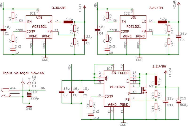
ZTEX USB-FPGA Boards require three different voltages: 1.2V, 2.5V-2.6V, and 3.3V, which must be supplied externally. This can be achieved using Power Supply Modules, Experimental Boards, or a user-specific design. To facilitate development in the latter scenario, three reference...
Most individuals are unaware that there are typically over a dozen battery backup systems present in their homes. The average American has around 18 battery-backed devices in their household. These battery backup systems protect crucial, expensive, or portable electronics...
With the rapid advancement of microelectronics and technology in information systems, digital technology represented by microcontrollers is evolving continuously. Microcontrollers are characterized by their small size, low power consumption, high expandability, and convenience in control functions. They are widely...