
Battery Backups in Consumer Electronics

The circuit design for a battery backup system typically involves several key components: an AC-DC converter, a battery management system, and a load output section. The AC-DC converter is responsible for transforming the incoming alternating current from the wall outlet into direct current. This conversion is achieved using a bridge rectifier composed of four diodes arranged in a specific configuration. The diodes allow current to flow in one direction, effectively converting the AC input into a pulsating DC output.
Following the rectification process, a smoothing capacitor is employed to reduce the ripple voltage present in the DC output, providing a more stable voltage level for charging the battery or powering devices. The battery management system is crucial for monitoring the state of charge of the battery, ensuring it is charged correctly and preventing overcharging or deep discharging, which could damage the battery.
The load output section connects to the devices requiring power, allowing them to draw from the battery or the AC supply as needed. This section may include additional circuitry for voltage regulation to ensure that the output voltage remains stable, regardless of the load conditions.
In summary, the integration of these components within a battery backup system ensures reliable operation of critical devices during power outages or fluctuations, providing peace of mind and uninterrupted service for essential electronics.Most people don`t know it, but there are usually over a dozen, battery backup systems in your home already. The average American around 18 battery backed up devices in their home. These battery backup systems backup the crucial, expensive, or mobile electronics, right under your nose.
Examples of battery backed up consumer electronics including the SMOKE ALARMS that beep in the night. Other examples include: wireless or satellite phones, laptop computers, MP3 players, tablet computers, and a variety of GPS devices all qualify. The battery on board design allows consumers to plug their appliances and electronics directly into any power grid without worry.
Other devices just run on Direct Power rather than the Alternating power that comes from the wall. Many consumer plugs change this power to Direct Current, the same type of power that comes from a battery inside the plug. A battery discharges and is charged with DC power or Direct Current, so by switching the current, inside the power plug, the accessory can be smaller and lighter.
The photo at right shows a number of different types of AC-DC wall plugs that actually charge the batteries, or circuits of your electronics, right now. These AC-DC transformers convert the alternating current into a positive and negative current on the appropriate wires.
Each has a rating clearly marked on the power supply that shows the maximum output voltage, and amperage. The power from the wall is AC power, Alternating Current, or a positive and negative voltage on one wire, alternating at 50 - 60 times a second.
The other wire is the return path to ground. The return path allows for a safe circuit to form, and the power can flow. To separate the positive and negative voltage from each other, a series of 4 diodes are needed and a bridging circuit. Basically the design routes AC power, through one of 4 one way doors, to the positive or negative wire, making it into DC power.
This DC power can then be used to charges batteries, run DC motors, etc. Below is an example of a circuit that makes a DC power supply: A battery should be used to fill in the gaps left in a bridging circuit. Basically a bridging circuit takes both positive and negative power from the same wire, and separates it.
However, as the power switches back and forth, small gaps are left. If you look at a bridging circuit diagram it would look something like the one to the right. At 60 hz, there would be 120 holes per second in the power available (the dotted line) as the system switches through positive and negative Alternating Current. A battery takes the peaks as a charge, and fills the valleys as seen by the solid line in the diagram.
Yet again, the UPS design foils a circuitry problem. This page is designed to start you on your educated way. This information is in no way complete, nor does it include safety information. You must take the time to understand that power at these voltages and with these circuits can be hazardous, even kill you. Please take the time to learn to do this safely. 🔗 External reference
Related Circuits
This is a simple NiCd battery charger powered by solar cells. A solar cell panel or an array of solar cells can charge a battery at more than 80% efficiency, provided the available voltage exceeds the fully charged battery...
A simple NiCd charger can be constructed using commonly available components and an inexpensive LM317 or 78xx voltage regulator. It incorporates a current limiter made up of resistor R3 and a transistor, allowing it to charge multiple cells until...
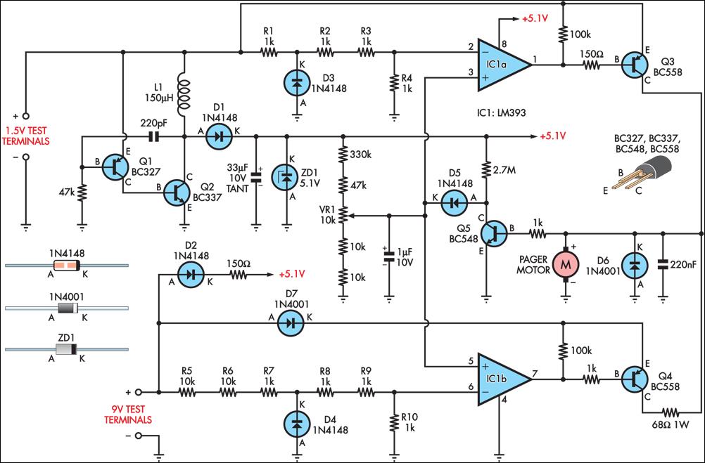
Many blind and deaf-blind individuals utilize portable electronic devices to assist in their daily activities; however, testing the batteries used in such equipment can be challenging. While talking voltmeters are available for the blind, there is no commercially available...
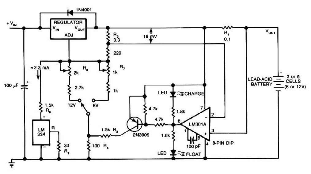
The schematic for this charger is straightforward. It is designed to charge a Gel Cell or other lead-acid types. This simple battery level monitor circuit can indicate the charging process in a 12 Volt lead-acid battery or tubular battery....
This project originated from the need for a Li-ion charging circuit that offers more flexibility than typical do-it-yourself circuits while being more affordable than programmable computerized chargers. The primary objective was to design, build, test, and share a charger...
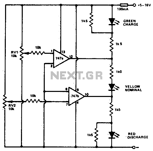
This circuit monitors car battery voltage and indicates nominal supply voltage, as well as low or high voltage conditions. RV1 and RV2 are used to adjust the thresholds at which the red/yellow and yellow/green LEDs activate or deactivate. For...