
quick jobs h bridge circuit to drive

The circuit design for controlling a motor using solid-state relays (SSRs) and the ADAM-4068 device involves several key components and considerations. The ADAM-4068 serves as a communication interface, allowing for the transmission of control signals to the SSRs through RS-485 serial communication. Each SSR is capable of managing high current loads, making them ideal for motor control applications.
To set up the circuit, the output from the ADAM-4068 is connected to the input terminals of the SSRs. The output signal from the ADAM is configured to switch to a "high" state when motor activation is required. This high signal enables current to flow from the common terminal (COM) to the normally open terminal (NO) of the SSR, effectively closing the circuit and powering the motor.
It is essential to ensure that the SSRs are correctly oriented in the circuit to prevent damage. The SSRs are designed to allow current to flow in a single direction; therefore, it is crucial to connect the positive and negative terminals correctly. The correct wiring configuration will ensure that when the control signal is activated, the SSR allows current to flow from the motor's power source through the SSR to the motor itself.
In addition, proper heat dissipation measures should be implemented, as SSRs can generate heat during operation, especially when controlling high currents. Heat sinks or proper ventilation should be considered to maintain optimal operating temperatures and ensure the longevity of the SSRs.
Overall, the combination of the ADAM-4068 and SSRs provides a robust solution for motor control in robotic applications, allowing for precise control and reliable operation. Proper attention to circuit design, component orientation, and heat management is vital for successful implementation.8 solid-state-relay (SSR) and ADAM-4068 (Serial-I/O device) and ask me to wire a circuit to control a motor for his robot. ADAM-6048 is a handy device that let you control digital input and output via RS-485, serial communication given a protocol in its manual.
Output of ADAM is rated at 0. 5 ampere so I use it to control the SSR which can operate up to 40 ampere each. When output set to "high", current will able to flow from COM to NO. Best to imagine it as a simple switch, when push both pin will connect and let a current flowing. Then pin 1 and pin 2 of SSR will connect and let a (high) current passthrough the motor. Unlike normal relay, SSR let current pass in only one direction, from pin 2 to pin 1 and from pin 4 to pin 3 as I indicate + and - sign in above diagram. I blown 2 SSR because of this ignorance! 🔗 External reference
Related Circuits
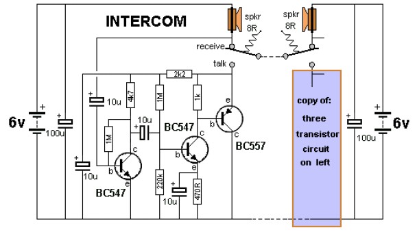
The key to avoiding instability (motor-boating) in a high-gain circuit is to power the speaker using a separate power supply. This circuit design allows for the connection of one or two additional stations. It is recommended to construct the...
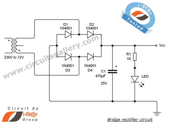
A rectifier is an electronic circuit that converts AC voltage to DC voltage. It can be implemented using a combination of capacitors and diodes. The unique property of diodes, which allows current to flow in a single direction, is...
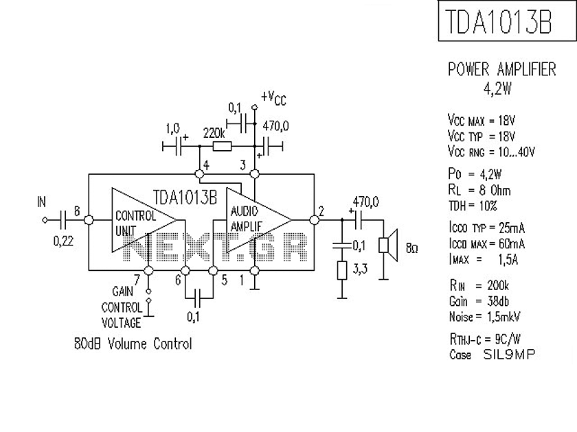
The following is a circuit for a 4-watt audio amplifier. The amplifier utilizes an integrated audio amplifier chip, TDA1013B, which is capable of delivering an audio power output of up to 4W at an 8-ohm load. Its wide supply...
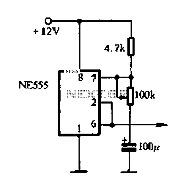
Automatic color holiday lights circuit The automatic color holiday lights circuit is designed to control the operation of decorative lights during festive seasons. This circuit typically utilizes a microcontroller or a timer to manage the sequencing and color changes...
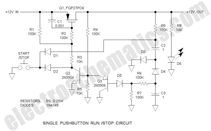
There are solutions to this problem—mechanical (push On/push Off switch), electromagnetic (latching relay), and electronic (CMOS logic), but few (if any) go... In addressing the problem of circuit control, several methods are available, including mechanical, electromagnetic, and electronic solutions. Mechanical...
At low output power, up to 18 W, the device functions as a standard BTL amplifier. When a greater output voltage swing is necessary, the internal supply voltage is increased using external electrolytic capacitors. This momentarily elevated supply voltage...