
diode bridge rectifier circuits
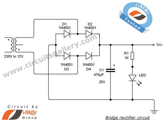
During the positive half cycle of the secondary voltage, diodes D2 and D3 are forward-biased, while diodes D1 and D4 are reverse-biased. Consequently, the current flows through D2, the load, and then D3. During the negative half cycle of the secondary voltage, diodes D1 and D4 become forward-biased, while diodes D2 and D3 are reverse-biased, allowing current to flow through D4, the load, and D1. For a time period of t=1s, the input voltage increases, causing the capacitor to charge up to the peak value of the input. After t=1s, as the input voltage begins to decrease, the voltage across the capacitor reverse-biases diodes D2 and D4, preventing them from conducting. The capacitor then discharges through the load, leading to a decrease in the voltage across the capacitor. When the peak voltage exceeds the voltage across the capacitor, diodes D2 or D4 become forward-biased, allowing the capacitor to recharge to the peak value. This cycle continues, resulting in a nearly smooth DC voltage output.
In a typical full-wave bridge rectifier circuit, the four diodes are arranged in a bridge configuration allowing for efficient rectification. The diodes are usually silicon-based, which is standard for rectification applications due to their low forward voltage drop and ability to handle high currents. The output of the bridge rectifier can be smoothed using an electrolytic capacitor, which filters the rectified voltage to reduce ripple, providing a more stable DC output.
The design of the transformer is also critical; a step-down transformer reduces the AC voltage to a manageable level for the rectification process. The choice of transformer affects the output voltage and current capabilities of the rectifier circuit. The rectifier's performance can be further enhanced by incorporating additional filtering stages or voltage regulation components, ensuring that the output voltage remains stable under varying load conditions.
Overall, the bridge rectifier is a vital component in power supply design, widely used in various applications, from simple hobby projects to complex electronic systems. Understanding its operation and characteristics is essential for anyone involved in electronics.What is a rectifier A rectifier is an electronic circuit that converts AC voltage to DC voltage. It can be implemented using acapacitor diodecombination. The unique property of diodes, permitting the current to flow in a single direction is utilized in here. Now what is a bridge rectifier Bridge rectifier is a full wave rectifier circuit using th e combination of four diodes to form a bridge. It has the advantage that it converts both the half cycles of AC input into DC output. Rectifiers are one of the basic electronic circuits. If you are an electronic hobbyist then this tutorial will help you to get started with your lessons in electronic circuits. A good bridge rectifier power supply (rectifier applications) is essential to start your home electronics lab.
Below is the full wave bridge rectifier schematic and operation explanation in detail. NOTE:You can use step down center tapped transformer as well as ordinary step down transformer. If you choose a center tapped transformer it is possible to change the output DC. By connecting middle point and a terminal point of transformer to rectifier or by connecting both terminal points of transformer to the rectifier voltage can be changed. During the positive half cycle of secondary voltage, diodes D2 and D3 are forward biased and diodes D1 and D4 are reverse biased.
Now the current flows through D2 >Load >D3 During the negative half cycle of the secondary voltage, diodes D1 and D4 are forward biased and rectifier diodes D2 and D3 are reverse biased. Now the current flows through D4 >Load >D1 Upto a time period of t=1s input voltage is increasing, so the capacitor charges up to peak value of the input.
After t=1s input starts to decrease, then the voltage across the capacitor reverse biases the diodes D2 and D4 and therefore it will not conduct. Now capacitor discharges through the load, then voltage across the capacitor decreases. When the peak voltage exceeds the capacitor voltage, diodes D2 or D4 forward biases and as a result capacitor again charges to the peak value.
This process continues. Hence we get almost smooth DC voltage as shown in fig (3). 🔗 External reference
Related Circuits
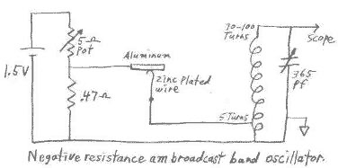
This circuit can be easily powered from a 1.5 volt battery. One characteristic of N type negative resistance devices is that they typically require a very low bias source resistance in order to keep the bias voltage stable within...
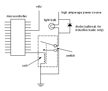
Digital output from a microcontroller is typically a low-amperage signal. For example, when a pin is set HIGH on the microcontroller (in Wiring/Arduino, it is digitalWrite(somePin, HIGH);), the voltage from that pin is usually +3.3V or +5V, with the...
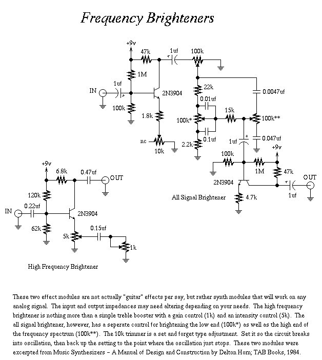
A collection of guitar fuzz, preamp, and operational amplifier (op-amp) electronic circuits and schematics designed for various guitar effects and distortion effects. This compilation includes a diverse range of electronic circuits that cater to guitarists seeking to enhance their sound...
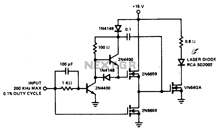
A faster driver can supply higher peak gate current to switch the VN64GA very quickly. The circuit uses a VMOS totem pole stage to drive the high power switch. The described circuit employs a high-speed driver to enhance the switching...
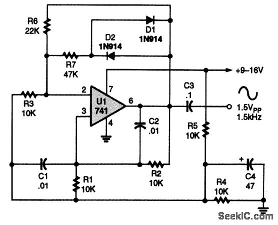
A 741 operational amplifier is configured within a Wien-bridge audio sine-wave oscillator circuit. The components C1, C2, R1, and R2 are responsible for determining the operating frequency of the circuit. By utilizing NPO capacitors and metal-film resistors, the oscillator...
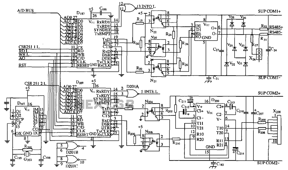
As shown in the figure, D187 is a universal asynchronous receiver-transmitter (UART). Its RX/TX signals are received through optocouplers N21, N22, and N29, facilitating RS-485 communication. The interface receiver/transmitter D28 and microprocessor D211 are completely optically isolated. D197 serves...