
Single Pushbutton Run-Stop Circuit

In addressing the problem of circuit control, several methods are available, including mechanical, electromagnetic, and electronic solutions. Mechanical solutions typically involve a push On/Push Off switch, which provides a straightforward means of toggling power states. This type of switch is user-friendly and requires no additional components; however, it may not be suitable for applications requiring remote control or automation.
Electromagnetic solutions, such as latching relays, offer an alternative that can maintain their state without continuous power. A latching relay operates by using an electromagnetic coil to toggle between two stable states. This type of relay can be advantageous in applications where power conservation is critical since it does not require a constant power supply to maintain its position.
Electronic solutions, particularly those utilizing CMOS (Complementary Metal-Oxide-Semiconductor) logic, present a highly efficient and versatile option for circuit control. CMOS technology enables low power consumption and high noise immunity, making it suitable for a wide range of applications. A CMOS-based circuit can be designed to perform complex logic operations, allowing for sophisticated control mechanisms that can be tailored to specific requirements.
Each of these solutions has its advantages and limitations, and the choice among them will depend on the specific application requirements, including factors such as power consumption, complexity, and the need for manual versus automated control.There are solutions to this problem—mechanical (push On/push Off switch), electromagnetic (latching relay) and electronic (CMOS logic), but few (if any) go.. 🔗 External reference
Related Circuits
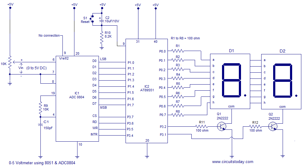
A simple 0-5 digital voltmeter utilizing the 8051 (AT89S51 microcontroller) is presented, accompanied by a circuit diagram and assembly language (ASM) code. This digital voltmeter is designed for straightforward voltage measurement. The circuit employs an AT89S51 microcontroller, which serves as...
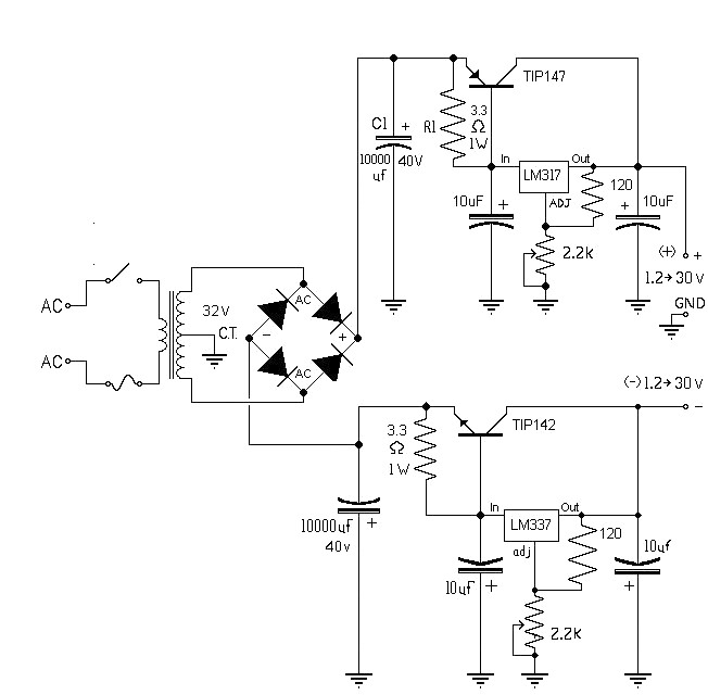
The 10A variable power supply circuit is symmetrical and can provide a symmetrical output voltage ranging from ±1.2 volts to ±30 volts DC, with a maximum current of 10A. This circuit utilizes symmetrical variable voltage regulators LM317 and LM337,...
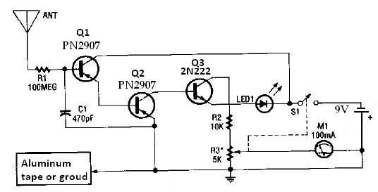
This ion detector circuit is designed to sense static charges and free ions present in the air. It is capable of detecting the presence of free ions, static electricity, or high voltage leakage. The project utilizes a short whip...

The device is referred to as the Itsy Bitsy USB Lamp. This concept is remarkably straightforward, raising the question of why it had not been conceived earlier. Originating as a student project at Massey University in Wellington, New Zealand,...
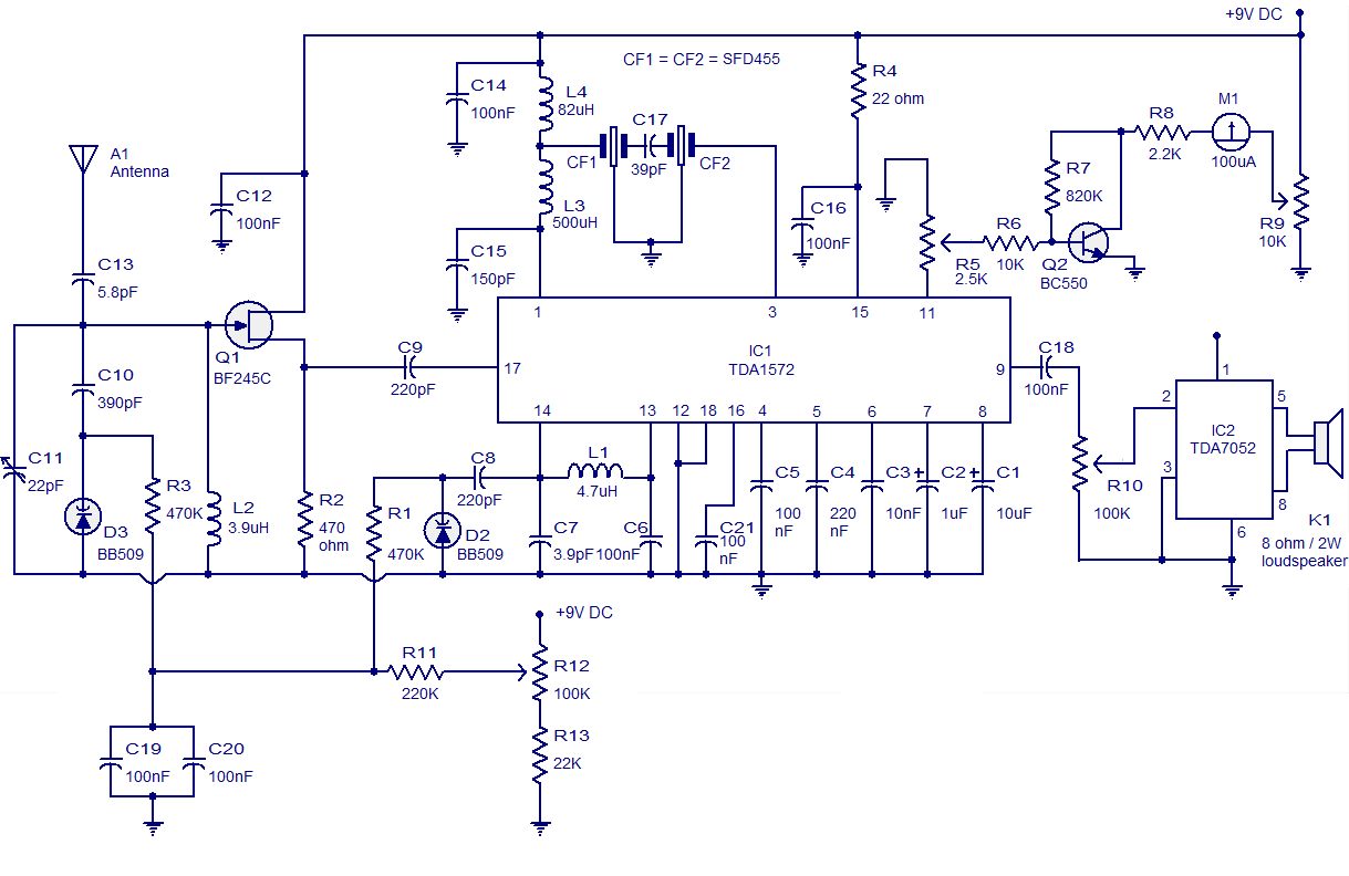
High-quality AM radio circuit based on the TDA1572 IC. The AM radio receiver circuit operates from 9V DC and has a 1W output power. It requires a minimum number of external components. The AM radio circuit utilizing the TDA1572 integrated...

A simple frequency meter or frequency counter circuit featuring an LCD display and an AVR microcontroller. This includes a DIY schematic circuit diagram and embedded C code. The frequency meter circuit is designed to measure the frequency of input signals...