
Quick Multiconductor Cable Tester

The described circuit functions as a cable tester for an eight-conductor cable, utilizing a 555 timer integrated circuit (IC1) and a decade counter (IC2), specifically the 4017 model. The 555 timer is configured in astable mode, generating a continuous square wave output that serves as a clock signal for the 4017 decade counter. The output of the 4017 is connected to a series of LEDs, which illuminate in sequence as the counter increments with each clock pulse from the 555 timer.
The cable under test is connected between two points labeled PL1 and PL2, which correspond to the individual conductors of the cable. As the counter cycles through its outputs, each LED represents a specific conductor of the cable. Under normal operating conditions, each LED should light up in a predetermined sequence, indicating that each conductor is functioning correctly and is properly connected.
In the event of miswiring within the cable, the sequence of illuminated LEDs will not follow the expected order, providing immediate visual feedback regarding the wiring error. Furthermore, if there is a short circuit or an open circuit condition within the cable, certain LEDs will fail to light up entirely. This behavior allows the user to quickly diagnose faults in the cable, such as shorts between conductors or breaks in the wire.
To implement this circuit, it is essential to ensure that the 555 timer is correctly configured to produce an appropriate frequency for the 4017 to operate effectively. Additionally, the LEDs should be connected with suitable current-limiting resistors to prevent damage from excess current. Overall, this circuit serves as an efficient tool for testing multi-conductor cables, simplifying the troubleshooting process for electronic and electrical applications. This circuit can be used to check up to an eight-conductor cable. IC1, a 555 timer, drives decade counter IC2, a 4017. Each LED should light in sequence. The cable to be tested is connected between PL1 and PL2. If the cable is miswired, the LEDs will light out of sequence. If it is shorted or open, some LEDs will not light.
Related Circuits
This indicator shows through a dual-LED see if a fuse is intact. The module is designed for 230 V AC. The green LED illuminates when the fuse is still good, the red lights when the fuse is broken. Perhaps...
Most telephone equipment today utilizes a DTMF receiver integrated circuit (IC). A widely used DTMF receiver IC is the Motorola MT8870, which consists of 18 pins and is employed in telephones and various other applications. When projects utilizing this...
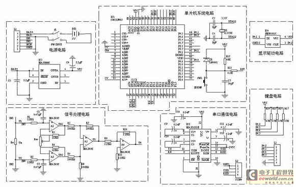
A one-chip computer has been utilized to design this survey meter, which directly displays the measured resistance on an LCD screen. The measurement range extends from 0 to 9999 kΩ, and the device can simultaneously store the measured data,...
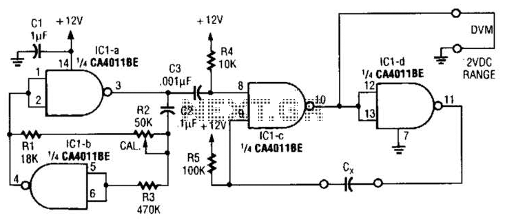
This circuit is designed for capacitor matching applications. The DC output voltage is directly related to the capacitance values of capacitor Cx. The specified circuit values are intended for capacitors in the 0.01 microfarad range; however, they can be...

This device functions as a convenient tool for testing infrared (IR) remote control transmitters used with televisions, VCRs, and similar devices. The IR signals emitted from a remote control are detected by the IR sensor module within the tester,...

The ML7005 is a multi-functional DTMF transceiver LSI that incorporates a DTMF signal generator, a DTMF signal receiver, a call progress tone generator, a call progress tone detector, and a FAX (FX) signal detector. Each functional block can be...