
Quiz Circuit PCB
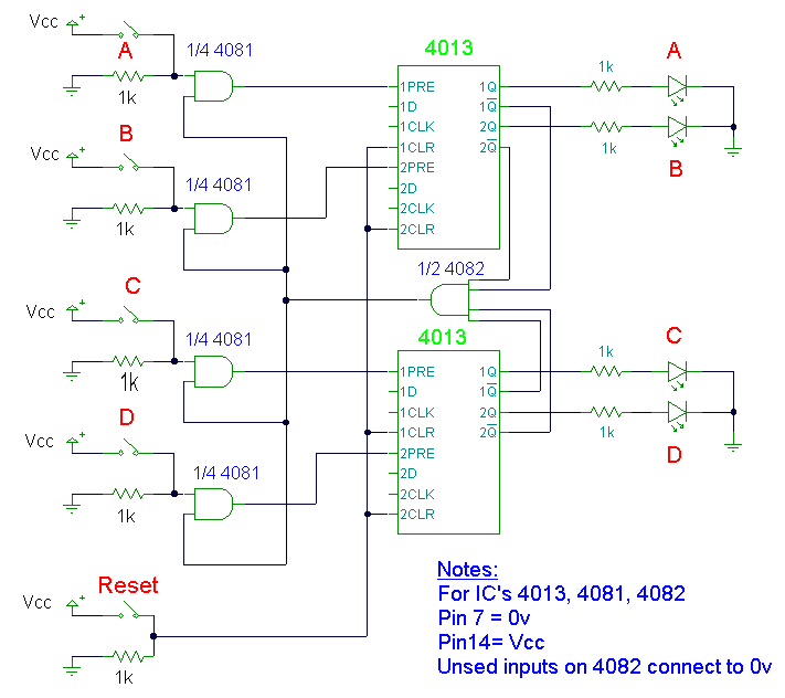
The quiz circuit design is structured to facilitate a simple yet effective interactive experience. The four input switches, labeled A, B, C, and D, are strategically placed to ensure easy access for participants. Each switch is connected to a corresponding two-input AND gate (4081), which serves to process the input signals. The output of each AND gate is linked to the preset input of the dual 4013 D-type flip-flop, which is the core of the circuit's memory function.
The bistable latch configuration of the 4013 allows the circuit to maintain a stable state once an input is activated. When a participant presses one of the input switches, the corresponding AND gate receives a high signal, triggering the preset of the flip-flop. This action sets the Q output high, illuminating the associated LED, while simultaneously pulling the NOT Q output low. The change in the NOT Q output state results in the AND gate (4082) output going low, effectively disabling all other inputs and preventing any other LEDs from lighting until the reset switch is activated.
The reset switch is critical for returning the circuit to its initial state. When engaged, it clears the flip-flops, turning off all LEDs and resetting the outputs to their default logic levels. This functionality ensures that the quiz can be restarted easily after each round.
The design accommodates a wide range of supply voltages, making it versatile for various applications. The use of CMOS technology allows for low power consumption, which is advantageous in battery-operated scenarios. Alternatively, the circuit can be implemented using TTL logic, providing flexibility in component selection based on availability and desired performance characteristics.
In summary, this quiz circuit offers a robust and interactive solution for multiple participants. Its reliance on standard ICs and simple logic design makes it an accessible project for electronics enthusiasts and professionals alike. The incorporation of heavy-duty push-button switches enhances reliability during use, ensuring that the circuit performs optimally under stress.I`ve had a few requests for a quiz circuit, so here is a 4 input design which can easily be modified. Maybe, I should write the application notes in the style of a game show host. This design uses four IC`s and has four input circuits and four independent outputs and a single master reset switch.
The outputs here are LED`s but may be modified to d rive lamps or buzzers. Only one output LED can be lit at any time. The first person to press their input switch, A, B, C, D will light the corresponding output LED, disabling the other inputs. The circuit uses all CMOS IC`s part numbers shown on the diagram. The supply voltage may be anything between 3 and 15 volts. Alternatively, it may be built using equivalent TTL IC`s and powered on 5 volts. The main component in this circuit is a bistable latch, here it is based on the dual 4013 D-type flip flop.
Pressing the reset switch will clear all flip flops and extinguish any lit LED`s. Under this condition the Q outputs will all be low (logic 0) and NOT Q outputs will be high (logic 1). All four NOT Q outputs are fed to a 4 input AND gate, the 4082 whose output will also be high. The output of the 4082 is wired to one input of each 2 input AND gate (4081). Switch inputs A, B, C, D are all non latching push button switches, the first person to press their switch will cause the corresponding AND gate (4081) to go high and trigger the preset input of the 4013 D-type flip flop.
This will latch and light the appropriate LED. Also the triggered flip flop will have its NOT Q output, set at low, this changes the 4082 output to low and prevents any further triggering of the other flip flops. Switch contact de-bouncing is not required as the first press will latch one of the bistables. Pressing the reset switch, restores the circuit to its former state. I would recommend using heavy duty push button switches, as in use they are likely to be under some stress.
🔗 External reference
Related Circuits
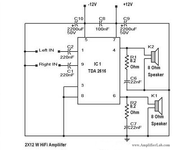
Various types of amplifiers include power amplifiers, audio amplifiers, tube amplifiers, stereo amplifiers, sensor amplifiers, RF amplifiers, sound amplifiers, and video amplifiers. Amplifiers are critical components in electronic circuits, serving to increase the amplitude of signals. Each type of amplifier...
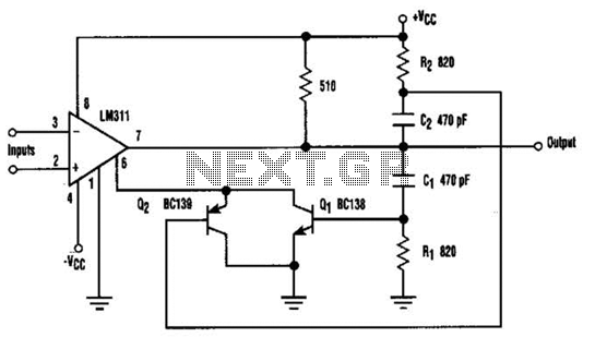
When the comparator's output transitions from low to high, the rising edge of the output pulse, differentiated by the Cl/Rl chain, activates Ql. This action blocks the comparator via its strobing input and maintains its output state for a...
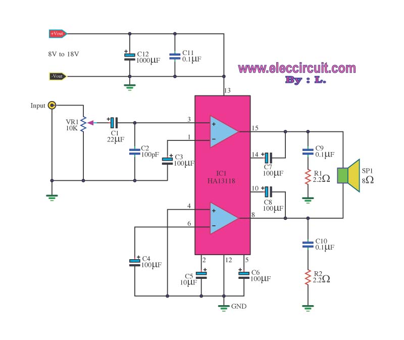
The amplifier circuit utilizes the HA13118 IC, a Hitachi component designed to deliver 18 watts of output power. This integrated circuit operates as a Class AB amplifier. The HA13118 IC is a versatile audio amplifier designed for high-fidelity applications, providing...
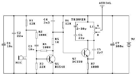
The tuned coil L1 has two output tap points for the antenna connection, labeled "A" and "B." Both outputs are low-level, allowing the user to select between a stable low range or a more unstable but higher range. Tap...
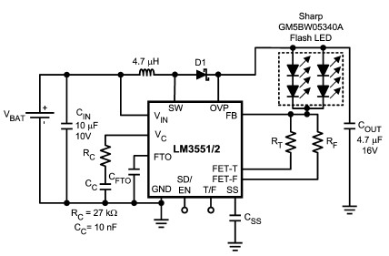
The LM3551 and LM3552 are fixed frequency, current mode step-up DC-DC converters featuring two integrated NFETs. These devices facilitate the design of a straightforward and highly precise LED brightness control system. They are capable of driving loads up to...
R2 controls the charging speed of capacitor C1. At a specific charge level, C1 triggers transistors Q1 and Q2, which release a 9-volt pulse. This pulse generates a clicking sound. The discharge process of the capacitor involves it charging...