
transistors How does this circuit diagram work
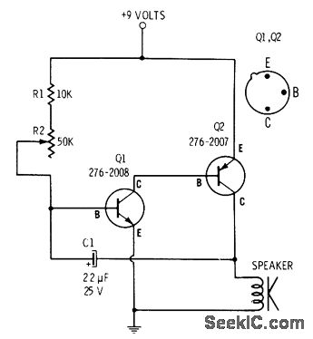
In this circuit, resistor R2 is strategically placed in series with capacitor C1 to regulate the charging rate of C1. The time constant of the RC circuit, defined as τ = R2 × C1, determines how quickly C1 charges to approximately 63% of the supply voltage. Once the voltage across C1 reaches a predetermined threshold, it activates the base of transistor Q1. This transistor, in turn, drives transistor Q2, allowing current to flow through the load, producing the desired 9-volt output.
The interaction between the capacitor and the transistors is crucial for the operation of this circuit. Capacitor C1 functions as a timing element, storing energy and releasing it when the voltage surpasses the trigger point for Q1. The discharge occurs rapidly once the threshold is crossed, effectively transitioning from charging to discharging. This transition is facilitated by the inherent characteristics of the transistors, which allow for rapid switching.
The clicking sound produced is a result of the sudden release of energy stored in C1. The frequency of this sound is influenced by the values of R2 and C1, as they dictate the charging and discharging cycles. Understanding the precise moment when C1 discharges and the factors that contribute to the cessation of charging can be explored further by analyzing the circuit’s feedback mechanisms and the characteristics of the transistors involved.
In summary, the circuit's functionality hinges on the interplay between R2, C1, Q1, and Q2. The design effectively utilizes the properties of capacitors and transistors to create a timing mechanism that produces audible output, illustrating a fundamental principle in electronic circuit design.R2 controls how fast C1 charges, and I know that at a certain point C1 will trigger Q1 and Q2 to release the 9 volts (see 2). This 9 volt burst creates the clicking sound. How does the capacitor discharge I imagine that the capacitor will slowly charge up to a point, then let it out (presumably to Q1).
When does it let out Why does it stop it`s "charging" routine to discharge 🔗 External reference
Related Circuits
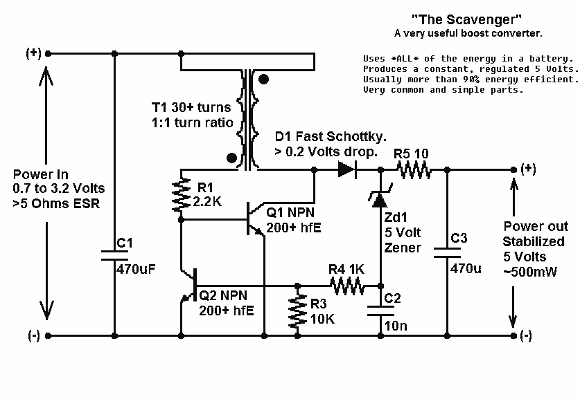
Presented here is a significant advancement in the design of simple, cost-effective, and efficient boost converters. To achieve an effective design, it is essential to convert current to voltage as efficiently as possible. This circuit excels in this regard. The...
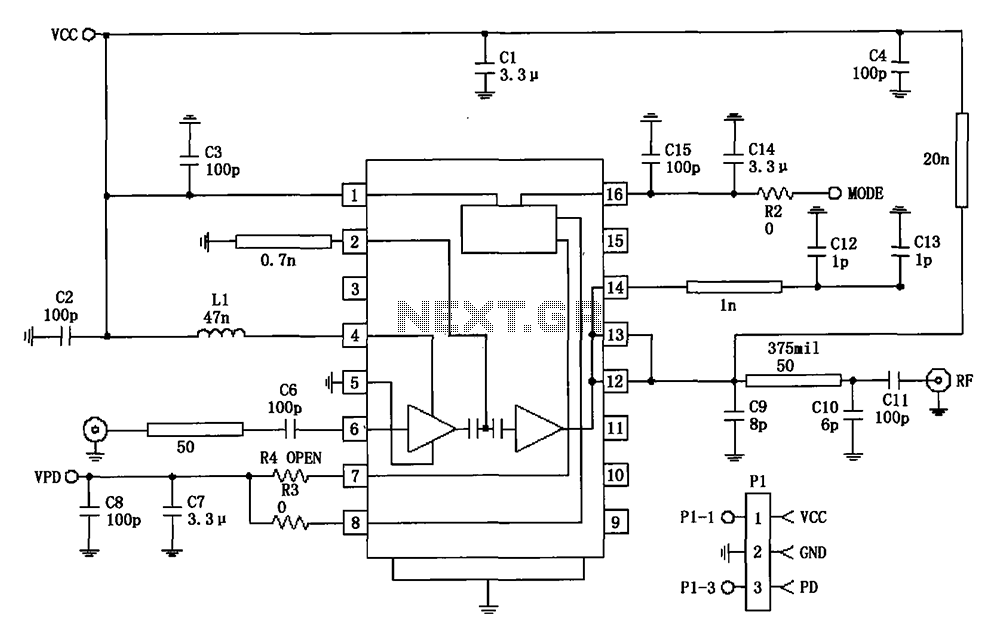
877 ~ 924MHz RF2152 power amplifier circuit diagram. The RF2152 is a high-performance power amplifier designed for applications in the 877 to 924 MHz frequency range. This amplifier is typically used in various RF communication systems, including wireless networks and...

This circuit includes an amplifier designed to deliver +10 dBm to an SBL series (Mini-Circuits) or a similar type of doubly-balanced mixer assembly. The circuit parameters are specified for 80 to 90 MHz crystals, although the values of the...
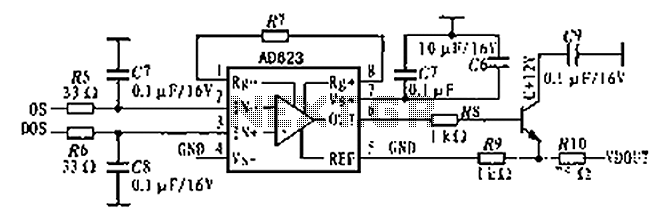
The AD623 is an integrated 3-way amplifier that can operate with either a single or dual supply. It features high common-mode rejection ratio (CMRR) and low voltage drift, along with programmable gain control via an external resistor. All components...
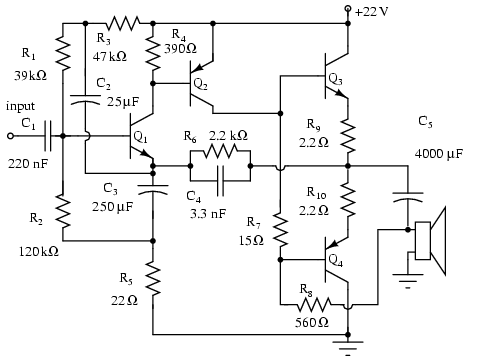
Note that Q3 and Q4 in the figure below are complementary, with Q3 being an NPN transistor and Q4 being a PNP transistor. This circuit is suitable for moderate power audio amplifiers. For a detailed explanation of this circuit,...
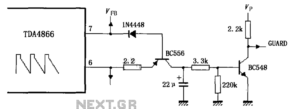
As illustrated in FIG TDA4866, the circuit consists of an external signal generator circuit protection. The internal protection circuit's role is to manage control, while the external protection circuit performs its functions. During normal operation, the vertical amplitude of...
Warning: include(partials/cookie-banner.php): Failed to open stream: Permission denied in /var/www/html/nextgr/view-circuit.php on line 713
Warning: include(): Failed opening 'partials/cookie-banner.php' for inclusion (include_path='.:/usr/share/php') in /var/www/html/nextgr/view-circuit.php on line 713