
R-C Twin-Tee Circuit Reduces Power-Supply Hum

The R-C twin-tee passive circuit is a fundamental design used for notch filtering, which effectively attenuates specific frequency components while allowing others to pass. The circuit operates by utilizing a combination of resistors and capacitors arranged in a symmetrical configuration. The critical parameters influencing the performance of the circuit include the quality factor (Q), which determines the sharpness of the notch, and the impedance, which affects the overall response of the circuit.
In this design, the choice of components is essential for achieving the desired filtering characteristics. The use of 47 µF electrolytic capacitors with a relatively high tolerance allows for flexibility in component selection while maintaining performance. The resistors, rated at 56 ohms, provide stability and precision in the circuit, ensuring that the notch frequency is accurately set at 60 Hz. The circuit's performance can be further enhanced by ensuring that the components used have low equivalent series resistance (ESR), which minimizes losses and maximizes the unloaded Q of the capacitors.
The construction of the circuit on a vector board allows for ease of assembly and modification, which is particularly beneficial in prototyping and testing phases. The die-cast aluminum enclosure provides protection against external interference and contributes to the circuit's reliability in portable applications.
As the demand for portable electronics continues to rise, the advantages of passive circuits, such as lower power consumption and reduced complexity, become increasingly significant. The R-C twin-tee circuit's ability to provide effective notch filtering in a compact form factor makes it an appealing choice for various applications, including audio processing and signal conditioning.
Future developments in the field may lead to enhanced component technologies that further improve the performance and efficiency of R-C twin-tee circuits, making them even more relevant in modern electronic designs.The R-C twin-tee passive circuit supplies band-reject (notch) filtering to portable applications. It has a circuit Q (loaded) of 0. 25. Satisfactory rejection can be achieved when the bridge is balanced (close tolerances of adjustable components) and the capacitor unloaded Qs (a function of capacitor ESR) are large compared to the circuit Q. A sche matic of a symmetrical twin-tee circuit is shown in the figure. The design equations are as follows: For convenience, an impedance of 50 © was used to test the circuit. The twin-tee circuit was designed for a notch frequency of 60 Hz. It was assembled on vector board (type 169P44C1) in a die-cast aluminum enclosure. The four capacitors are 47- F, 35-V electrolytics with a ±20% tolerance. The four resistors are 56- ©, 1/2-W metal-film types with a ±1% tolerance. The measured amplitude response of the 60-Hz twin-tee circuit is shown in the table. The choice of capacitors is crucial to realizing notch selectivity. The capacitors were obtained from Mouser Electronics per stock number 5985-AFK35V47. The surface-mount components have a maximum ESR of 0. 36 © at 20 °C and 100 kHz. These electrolytic capacitors are polarized, and correct polarities must be maintained throughout the circuit.
The coarse tolerances of the capacitors may adversely affect the reproducibility of the 60-Hz twin-tee circuit during manufacture. This probably could be mitigated by using single-turn, 100- © variable resistors in place of the two fixed, grounded shunt resistors.
With the advent of portable electronics equipment, passive circuits can be advantageous. They reduce battery current drain and eliminate some wiring. Passive R-C twin-tee circuits have been around for decades. 1 Hopefully, component tolerances and capacitor ESRs will improve. In the era of supercapacitors, surface-mount components, and enhanced pc-board materials, ongoing applications for R-C twin-tee circuits should be considered. 🔗 External reference
Related Circuits
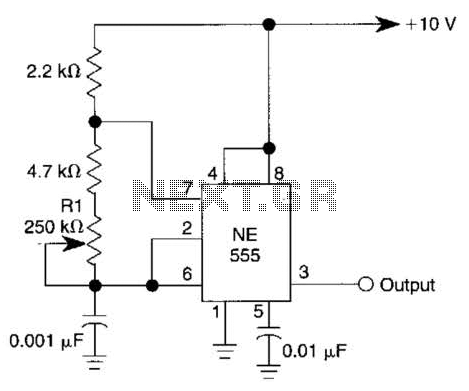
This simple square-wave generator produces a variable frequency output ranging from 2800 Hz to 80 kHz, as indicated by the specified values. The frequency can be adjusted using potentiometer R1. The square-wave generator circuit typically employs a combination of resistors,...
This is a simple circuit designed for an audio amplifier project to control the speaker output relay. The purpose of this circuit is to manage the relay that activates the speaker output in the audio amplifier. The circuit is...
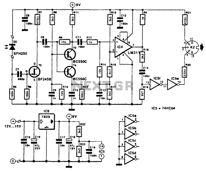
The receiver photodiode SFH250 is utilized to convert optical data pulses at a rate of 32.5 Kbps into electrical signals. The buffer T2 transmits these signals to a cascade amplifier consisting of transistors T3 and T4, followed by an...
This is a car alarm simulator that uses an LED as a simulation output. This simple circuit can indicate whether a car is running or not by detecting the voltage difference when the car is on or off. This...
A thermistor positioned as indicated creates a heat-activated sensor. Variations in temperature will modify the output of the operational amplifier, triggering the relay and illuminating the LED. Reversing the placement of the thermistor and the 47k resistor converts the...
The following circuit illustrates a Dancing LEDs electronic circuit diagram. This circuit is based on the LM358 integrated circuit. Features: IC1A amplifies the signal. The Dancing LEDs circuit utilizes the LM358 operational amplifier to create a visually appealing light display....
Warning: include(partials/cookie-banner.php): Failed to open stream: Permission denied in /var/www/html/nextgr/view-circuit.php on line 713
Warning: include(): Failed opening 'partials/cookie-banner.php' for inclusion (include_path='.:/usr/share/php') in /var/www/html/nextgr/view-circuit.php on line 713