
Variable Square Wave Generator Circuit

The square-wave generator circuit typically employs a combination of resistors, capacitors, and operational amplifiers or digital logic components to achieve the desired frequency output. The primary function of the circuit is to convert a steady DC voltage into a square wave signal, which can be utilized in various applications such as clock signals for digital circuits, audio tone generation, or modulation purposes.
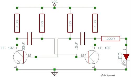
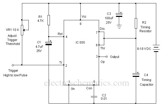
In this specific design, the frequency of the output signal is modulated by adjusting the resistance of potentiometer R1. This potentiometer is strategically placed in the timing circuit, which may include additional resistors and capacitors that define the charge and discharge times of the timing capacitor. By varying the resistance, the time constants of the charging and discharging cycles are altered, thus changing the frequency of the output square wave.
The circuit may also include a feedback loop that stabilizes the oscillation and ensures a consistent waveform. Additionally, the output stage of the circuit might incorporate a transistor or a buffer to drive the load effectively, ensuring that the square wave can be used to control other devices or circuits without significant signal degradation.
Overall, this square-wave generator is a versatile and essential component in electronic design, offering a simple yet effective means of generating variable frequency signals for a wide range of applications. This simple square-wave generator produces a variable frequency output of 2800 Hz to 80 kHz with the values shown. Frequency is adjusted with potentiometer Rl.
Related Circuits
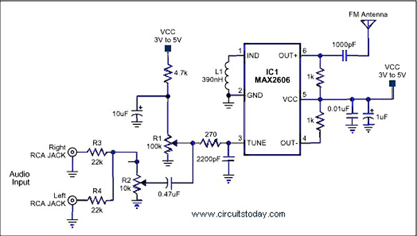
A simple single-chip FM transmitter circuit with a diagram and schematic using the IC MAX 2606, which is a high-performance voltage-controlled oscillator (VCO). The FM transmitter circuit utilizing the MAX 2606 is designed for efficient frequency modulation of audio signals....
The following circuit illustrates a VHF pre-amplifier circuit diagram. This circuit utilizes the BFS17 transistor. Features: designed for VHF applications. The VHF pre-amplifier circuit is essential for enhancing weak radio frequency signals in the VHF (Very High Frequency) range, typically...
An astable multivibrator is a switching circuit that alternates its output on and off for a designated time period. This device, also known as a free-running oscillator circuit, is primarily utilized to generate square waves over a specified duration....
Displeased with your younger brother's choice of TV channels? Frustrated by the volume level your spouse sets on the stereo? Looking to create a bit of mischief? This circuit effectively jams most infrared (IR) remote signals. It emits a...
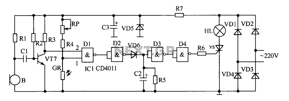
The delay-saving lamp circuit functions as a sound and light control delay energy-saving lighting system. It can directly replace a standard light switch without modifying the existing lighting circuits. In bright or daytime conditions, the sound control feature ensures...
A monostable multivibrator using the IC CD4538 is a precision device that functions as a monostable/astable multivibrator and is designed to avoid false triggering. This IC is suitable for various applications requiring precise timing cycles. The CD4538 offers improved...