
Automotive Circuits
The car alarm simulator circuit primarily consists of a voltage detection mechanism that monitors the electrical state of the vehicle. The circuit is designed around a voltage comparator, which is typically implemented using an operational amplifier (op-amp). The op-amp compares the voltage level from the vehicle's battery with a predefined reference voltage.
When the vehicle is turned on, the voltage at the op-amp's input exceeds the reference voltage, resulting in a high output signal. This output can be connected to an LED, which will illuminate to indicate that the car is running. Conversely, when the car is turned off, the voltage drops below the reference level, causing the op-amp output to go low, which turns off the LED.
Additional components that may be included in the circuit are resistors to set the reference voltage and capacitors for noise filtering. A potentiometer can also be integrated to allow for adjustable sensitivity of the voltage detection. The circuit may be powered by the vehicle's battery, ensuring it operates reliably under the conditions present in an automotive environment.
This car alarm simulator circuit serves as a useful tool for testing and demonstrating the functionality of car alarm systems, providing a visual indication of the vehicle's operational status in a straightforward and effective manner.This is a car alarm simulator which using the LED as a simulation output. This simple circuit can tell you whether your car is running or not by detecting the voltage difference when the car is on and off. This occurs because when your car. 🔗 External reference
Related Circuits
The 8-pin 555 timer is one of the most versatile integrated circuits (ICs) available, utilized in numerous projects. With minimal external components, it can be employed to construct various circuits, many of which do not pertain to timing applications....

When troubleshooting the 12V electrical system of an automobile, it is beneficial to have a simple voltage indicator tool instead of a voltmeter. This electronic circuit is powered by two AA batteries or two N cells, providing sufficient energy...

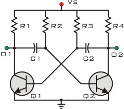
The circuit features a self-excited multivibrator composed of transistors VTi and VTZ. It includes an adjustment potentiometer RP and two RC networks that influence the transistors' parameters, specifically the timing for light activation and deactivation. The described multivibrator circuit utilizes...
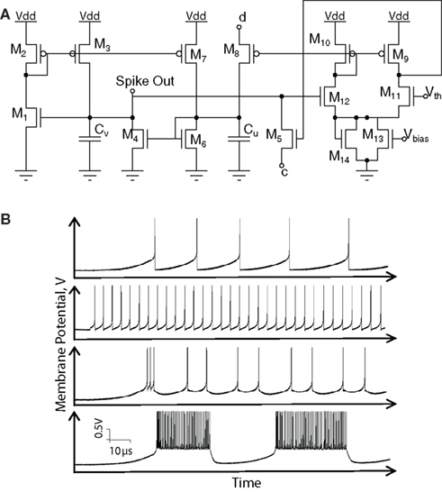
Hardware implementations of spiking neurons are highly beneficial for various applications, including high-speed modeling of large-scale neural systems, real-time operating systems, and bidirectional brain-machine interfaces. The specific circuit solutions for silicon neurons are dictated by the requirements of each...
This circuit is designed to drive a relay coil using a low power output, typically from an integrated circuit (IC) such as a 555 timer or a TTL/CMOS device. It facilitates the switching of high loads or loads requiring...
The Johnson 275 watt and Kilowatt Matchboxes are often seen as exaggerated and unfairly criticized. They are neither exceptional tuners nor poorly designed. The main drawbacks include the fixed coupling link and the fact that they are balanced voltage...
Warning: include(partials/cookie-banner.php): Failed to open stream: Permission denied in /var/www/html/nextgr/view-circuit.php on line 713
Warning: include(): Failed opening 'partials/cookie-banner.php' for inclusion (include_path='.:/usr/share/php') in /var/www/html/nextgr/view-circuit.php on line 713