
Radar Calibrator Circuit
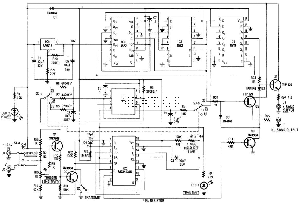
The circuit utilizes a 555 timer in astable mode to generate a continuous square wave signal. This signal is then fed into a frequency divider chain, which is composed of flip-flops that divide the frequency of the input signal by a predetermined factor. The output of this chain produces various frequency outputs corresponding to the desired Doppler shift values.
The Gunn diode, which operates at microwave frequencies, is modulated by the pulsed signal generated from the 555 timer. The modulation of the Gunn diode allows for the generation of microwave signals that can be utilized in radar systems. The Doppler effect is crucial for measuring the speed of objects, and the circuit is designed to provide specific modulation frequencies that correspond to the desired speed settings.
The preset speed settings (S3 a and b) are implemented using a switch mechanism, allowing users to select between different operational modes easily. This flexibility is essential for applications requiring accurate speed measurements in radar technology.
Overall, this circuit design is integral for enhancing the performance of radar systems by providing modulated microwave signals that can adapt to various operational requirements in both X-band and D-band radar applications. The combination of the 555 timer and the frequency divider chain ensures precise control over the output frequencies, facilitating reliable Doppler shift measurements. This circuit is basically a system that generates a pulsed modulation signal for a Gunn diode microwave oscillator. Several speed settings are preset (S3 a and b). A 555 timer is used with a frequency divider chain to produce Doppler shift equivalents of 25, 35, and 55 rnph,
for both X- and D-band radars. 🔗 External reference
Related Circuits
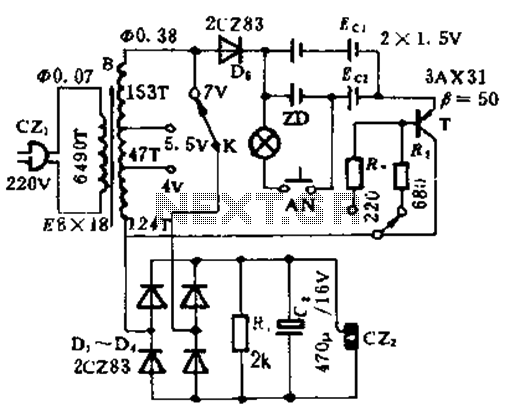
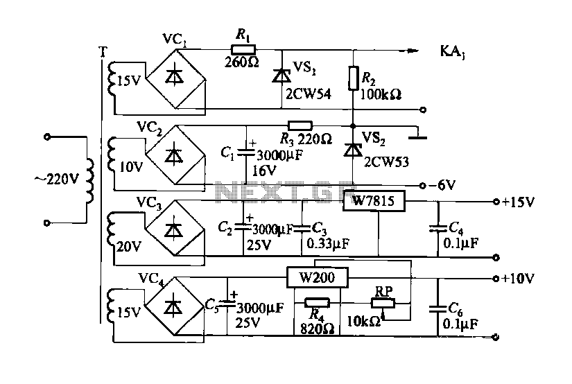
This circuit is designed for high current applications using nickel-cadmium rechargeable batteries, and it can also function as a general low-voltage DC power supply. The circuit consists of a charging section and a DC output section. K2 serves as...
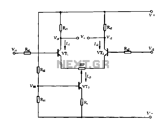
A differential amplifier with a constant current source is illustrated in Figure 1-27. As long as capacitor C3 is maintained at a constant value, capacitors C1 and C2 cannot be simultaneously increased or decreased, preventing voltage drift. The differential...
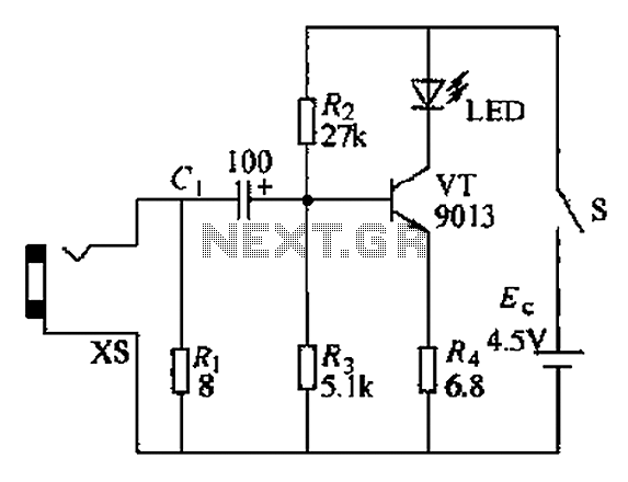
The circuit operates as a light-to-sound conversion system, featuring a light electric sound conversion circuit with two simple fiber optic connectors for experimental purposes. The electrical diagram illustrates the conversion circuit, where audio signals from a radio, music player,...
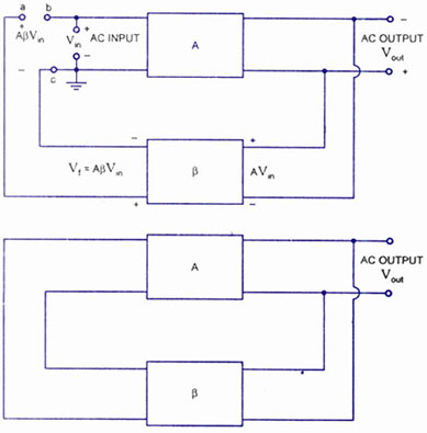
A feedback amplifier with a closed-loop gain, Af, greater than unity can be achieved through the use of positive feedback. This condition also fulfills the phase requirement, leading to the operation of an oscillator circuit. An oscillator circuit generates...
This document outlines a CMOS circuit designed for time adjustment in a spot welder. The circuit allows for the selection of a number of cycles, ranging from 1 to 99, with practical applications typically using around 10 cycles. The...
Solar panels operate at optimal parameters when positioned at the ideal angle to the sun. This alignment is achieved by rotating the solar panels to track the sun's movement. A DIY solar tracker system can be constructed using an...