
Low voltage DC power charger circuit
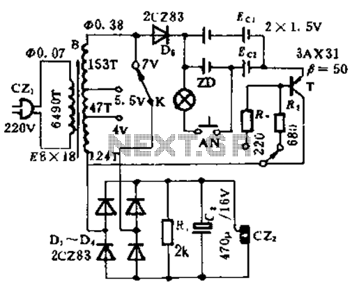
This circuit functions by integrating both a charging mechanism and a DC output feature, making it versatile for various applications. The charging section is responsible for replenishing the energy in nickel-cadmium batteries, which are known for their ability to deliver high current. The design allows for two distinct charging rates, controlled by the K2 switch, enabling users to select either a fast charge mode, which typically completes in about 4 hours, or a slow charge mode that extends the charging duration to approximately 14 hours.
The current limiting resistors, R2 and R3, play a crucial role in managing the charging current. By adjusting these resistors, the user can fine-tune the charging process to suit specific battery requirements, ensuring safe and efficient charging. This flexibility is particularly beneficial in scenarios where battery longevity and performance are critical.
The inclusion of the test circuit with components NA and ZD provides a visual indication of the charging status. Before charging begins, it is essential to install the rechargeable batteries properly. When the AN button is activated, the ZD indicator will provide feedback on the circuit's status. A lit ZD indicates that the circuit is functioning correctly, while an unlit ZD may suggest a fault or improper setup.
After the charging cycle has completed according to the set parameters, the ZD indicator will glow for 10 seconds, signaling that the batteries have reached full charge. This feature ensures that users can confidently utilize the circuit for powering various appliances, knowing that the batteries are adequately charged and ready for use. Overall, this circuit design effectively combines functionality and user-friendly features for managing rechargeable battery systems.This circuit can be used for large current after use nickel-cadmium batteries, rechargeable batteries, but also as a general low-voltage DC power supply. This circuit by the charging section and the dc output parts. K2 is the fast charge, slow charge selector switch, R2, R3 current limiting resistor, can change the size of the charging current. Typically, fast charge control in about 4h, slow charge about 14h. NA, ZD composition of the test circuit. Before charging, be fitted with rechargeable batteries. Press AN time, ZD matte or shimmer is normal, when the charging time to meet the requirements, according to AN, the ZD emitting be maintained 10s described above full power, so as for appliances.
Related Circuits
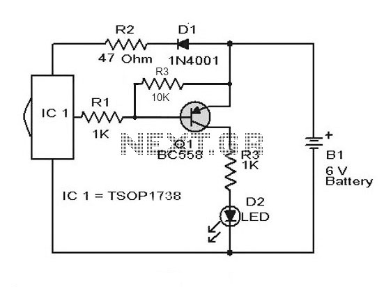
A simple remote control tester circuit with a diagram and schematic using the infrared sensor IC TSOP1738. An LED will blink when infrared waves fall on it, indicating the remote control is functioning. The remote control tester circuit utilizes the...
Electrical signals travel along the neurons in the brain and body, continuously transmitting information throughout the complex system. Without these signals, the body would function like a plant, with different parts unaware of each other's conditions, making animal life...
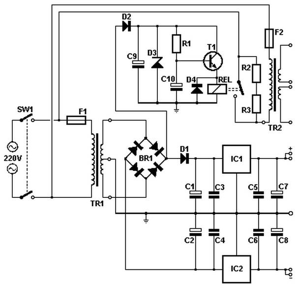
Soft power for a large transformer is implemented by using a series resistance of 100 ohms at 10 watts, or alternatively, two resistors of 47 ohms at 5 watts each in the primary circuit. The resistance is bypassed by...
This circuit displays a sound generator that simulates the siren of a British police car. The circuit is constructed using two timer IC 555. The sound generator circuit designed to simulate a British police car siren utilizes two 555 timer...
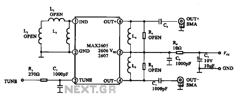
A low phase noise voltage-controlled oscillator circuit is presented, specifically integrated within the MAX2605-2609 voltage-controlled oscillator series. The circuit features a tuning voltage control terminal, allowing for adjustable oscillation frequency through a DC voltage input. The output of the...
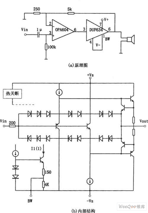
The provided image depicts a high-performance and low-power audio power amplifier circuit. The initial stage utilizes the MOSFET hi-fi operational amplifier OPA604, while the subsequent stage employs the high-speed buffer BUF634. Voltage series negative feedback is implemented between the...
Warning: include(partials/cookie-banner.php): Failed to open stream: Permission denied in /var/www/html/nextgr/view-circuit.php on line 713
Warning: include(): Failed opening 'partials/cookie-banner.php' for inclusion (include_path='.:/usr/share/php') in /var/www/html/nextgr/view-circuit.php on line 713