
Radio Control a two wheel robot from your PC
The electronic schematic for this project integrates several key components to facilitate wireless control of a mobile platform. The Basic Stamp microcontroller serves as the central processing unit, executing commands received via the PC's serial port. The communication occurs through a serial connection on pin 0, using a DB-9 or DB-25 connector, which is standard for serial communication interfaces.
The H-bridge SN754410 is critical for driving the motors, allowing for bi-directional motor control. Each motor's direction is determined by the logical high and low signals sent from the Basic Stamp. To manage the current draw and prevent overheating, multiple H-bridge chips can be stacked, with heat sinks attached to the ground pins to dissipate heat efficiently. The power supply for the motors is routed through pin 8 of the Basic Stamp, protected by a 3-amp fuse to prevent overcurrent conditions.
The 74HC14 inverter plays a dual role in this design. It not only reduces the overall current consumption of the Basic Stamp but also allows for the flexibility of controlling multiple motors with fewer bits. The logic configuration for motor control is straightforward: a high signal (1) activates the motor in one direction, while a low signal (0) reverses it. This configuration can be adjusted in software, and additional inverters can be added to eliminate any initial movement jump when the robot is powered on.
The project also includes provisions for optional features such as a power-on indicator light and a speaker for audio feedback, which can assist in troubleshooting during the development phase. The speaker is driven by pin 1 of the Basic Stamp, utilizing the PBASIC sound command for generating tones.
To complete the system, a serial cable is constructed according to the guidelines provided in the Basic Stamp manual, ensuring proper connections and functionality. The design can be further expanded by integrating additional sensors, such as bump or infrared sensors, using the remaining pins on the Basic Stamp.
Powering the system can be achieved through a dedicated DC transformer or batteries, ensuring compatibility with the motor's voltage requirements. The entire setup can be housed in a protective enclosure, with an optional antenna for enhanced wireless communication, making this project a versatile platform for further exploration in robotics and remote control applications.Well, it took some time and a few failed attempt, but here it is. A neat project that lets you control two wheels or tracks from your PC serial port with no wires attached. I have it working at 2400 baud and that is about as fast as I can think. We assume you have a PC, so what else do you need First a Basic Stamp. I am using the Stamp I, but a B asic Stamp II would be much better for later expansion. Next you need a transmitter and receiver. The best deal (and they work too) are ones made by Ming available from Circuit Specialist. The next piece of magic is from Acroname (built by TI). This H bridge chip takes care of two motors. I have mine running up to three amps by stacking them and adding cooling wings to the ground pins. Now we add a couple of 7805 regulators, a 74HC14 inverter, a resistor and a couple of capacitors and that`s all we need. Well, we need wire, a fuse, batteries and of course a two wheeled platform, but that`s another issue.
You may want to add a power on light and a speaker but for now they are optional. The Basic stamp is our brains. Pin 0 is our serin connection. I used pin 1 to drive a little speaker as explained in the PBASIC sound command. This is nice for troubleshooting the design. Pins 2-5 control our motors. Six and seven are left for other functions, like a bump sensor or a IR sensor, etc. The SN754410 is a great little chip. I just soldered them on top of each other until I had enough to handle 3 amps. The heat from this chip is transferred out through the 4 ground connections in the middle. I just cut out a piece of sheet metal and soldered it to both sides between the ground pins like vertical wings. Holding both motors stopped they get warm. Motor power goes to pin number 8. I am using a 3 amp fuse, should keep things in range. If your robot is smaller, one chip may be just right. The 74HC14 allows the use of only 4 bits. It also lowers the amp draw on the Stamp. With a motor you get two choices, forward or reverse right So if you need an extra bit you could cut it down to 3 bits, but you could not stop just one motor.
Logic for a single motor is a 1 puts the motor forward, a 0 is reverse. Then you bring the enable high and that is the direction you get. With this design you get a small jump when you start the robot. To prevent this you need to invert your bits in software and add another 74HC14 to correct this. Now you need to build the serial cable. The Basic stamp manual covers this well under the SERIN command. All you need is a DB-9 or DB-25 depending on your computer, 3 jumper wires and a 22k resistor. I added a diode to prevent a negative swing on the serial wire, but it appears to work fine without it. For the first test you can connect this up direct to the Basic Stamp. Later after everything is working, you can install the RF modules. Just connect the PC serial out to pin 0 and connect the grounds. The PBASIC stamp program is listed. This uses about half the memory so there is room for expansion still. Run this program on the Stamp then go to QBASIC and run the QBASIC listing. The 10 key pad allows you to control the robot`s direction. Okay, got the robot on a block of wood and the wheels spin the way you want Just reverse the motor wires, or change the logic in the PBASIC program if it is not correct.
Lets turn him loose now. Cut your ground and serin wire to pin 0. On the robot run these and 5 volts to the receiver connector as labeled. On the PC side, you need either batteries or a 6-12 volt DC transformer. Sorry, no 5 volts available from the serial port :(. Get one to match your robots batteries so it can charge them and then power your transmitter too. I used a transformer hooked to the 7805, soldered the wires and caps direct. Then attached the serial wire, ground, and 5 volts to the transmitter as labeled. Threw it all in a plastic box. And now the robot runs without any attachments. I even added an antenna to the box. It`s not connected, but it lets everyone know what the box is :). Basic stamp, this site will get you up to speed if the Stamp is new to you. Visit all the links before buying. I bought the starter kit, but you can save a lot if you do your homework and build your own cable. You can even download the manual and read while you order is on the way. Everything else is very common, even Radio Shack has the rest. But Circuit Specialists has everything, might as well get it from them when you order. Or Jameco ( ) sells the Stamp and has a great selection of cable ends, crimp tools, grab bags, etc. 🔗 External reference
Related Circuits
Many radio amateurs are interested in powering simple radio receivers using "free energy," which refers to energy obtained directly from the air via the receiver antenna. The circuits described can facilitate radio reception through a loudspeaker. However, questions remain...
A complete AM radio set based on the MK484 IC (formerly ZN414). It uses a PNP transistor and can drive a 150R loudspeaker. Chad has built a complete radio receiver using 1 IC and a single transistor. The IC...
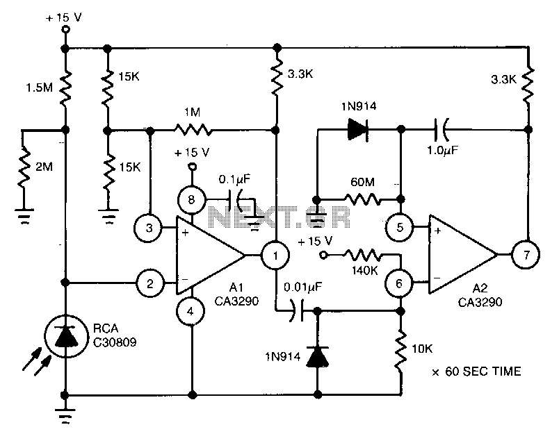
This circuit utilizes the CA3290 BiMOS dual voltage comparator to detect variations in the current of a light-emitting diode (LED). The output from the comparator triggers A2, a one-shot timer. If the light source to the photodiode is disrupted,...
The automatic sprinkler controller circuit consists of a +12 V power supply circuit, a light control circuit, and an irrigation control circuit, as illustrated in the accompanying figure. The +12 V power supply circuit includes a knife switch (Q),...
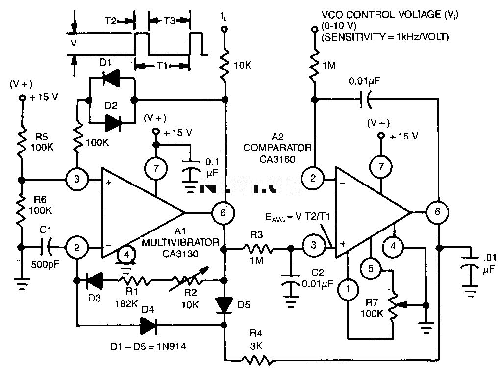
This circuit utilizes a CA3130 BiMOS operational amplifier as a multivibrator and a CA3160 BiMOS operational amplifier as a comparator. The oscillator exhibits a sensitivity of 1 kHz/V, with a tracking error of approximately 0.02% and a temperature coefficient...
This article outlines a reliable, straightforward, and universal method for interfacing Motorola mobile radios from the MaxTrac, Radius, and GM300 series with common repeater controllers. The information provided is also relevant for radio interfaces used in IRLP or EchoLink...