
Loudspeaking crystal radio receivers
The design of the receiver circuit aims to maximize the efficiency of energy extraction from the antenna while ensuring adequate audio output for loudspeakers. The push-pull emitter follower configuration is particularly advantageous in maintaining signal integrity and minimizing distortion, as it allows for effective current amplification without compromising the voltage levels necessary for audio fidelity. The careful selection of components, including the transformer and choke, is critical in achieving the desired performance characteristics. The emphasis on high-efficiency loudspeakers and optimal acoustic design underscores the importance of these factors in achieving satisfactory audio reproduction from a radio receiver powered by ambient energy. Overall, this approach offers a practical solution for radio amateurs seeking to explore the capabilities of free energy in their projects.A lots of radio amateurs have an interest to power a simplest radio receivers with the "free energy", i. e. the energy, taken by the receiver antenna directly from the air. The circuits described here can provide a radio reception using a loudspeaker. The question of how much power can get out of a signal from an antenna, and how to build a loudspe aking crystal set, was already discussed in the author`s articles [1, 2]. However the questions "how much power we need for loudspeaking reception " and "how to better use the power from the antenna ", still remain. According to the old reference books, to listening a voice of a broadcaster from the distance of 1 meter it takes the sound level of the loudspeaker about 60 dB.
In this case, the radiated acoustic power is 12. 6 W. The necessary electrical power can be calculated by dividing the radiated acoustic power by the energy conversion efficiency of the loudspeaker. For the common loudspeakers the energy conversion efficiency is about 1%. Thus we get the electrical power about 1mW. It is interesting to calculate the required power for loudspeakers to get the sound level of 60 dB. The calculation results for the different loudspeakers are presented in table 1. From the table 1 we see that we need to use the high-efficiency loudspeakers. The acoustic design of the loudspeaker systems is very important, the bigger speaker cabinets is better.
In the experiments the author used two loudspeakers type 4GT-2 in wooden cabinets with the enclosure volume of 50 liters. Horn loudspeakers has three times better efficiency because of the improved coupling efficiency between the speaker driver and the air and because of the directional characteristics of the produced sound waves.
The simple and effective loudspeakers was built by radioamateurs, they used paper, cardboard and plywood [3]. Horn loudspeakers with a bass reflex system with U-shaped design provides with the loudspeaker 6GD-1 efficiency of about 2.
3%, and at the low frequencies about 3. 4%. So, we found that the audio signal of 0. 2 mW is sufficient for the sensitive acoustic system. Analysis of the detector circuit leads to the conclusion that the current should be amplified, but not the voltage, because the voltage amplification could limit the peaks of the signal. Because of this it is wise to use in this circuit the push-pull emitter follower, based on the complementary pair of transistors working in class AB.
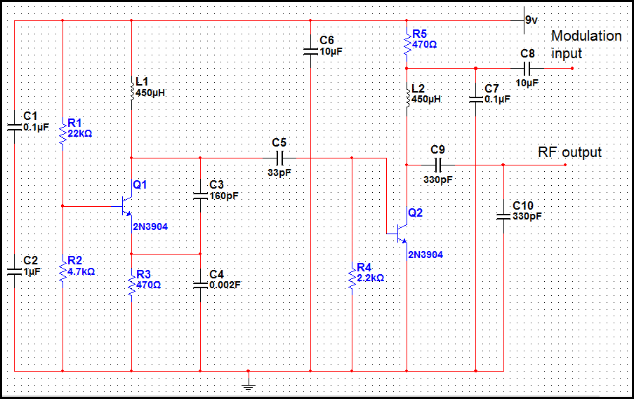
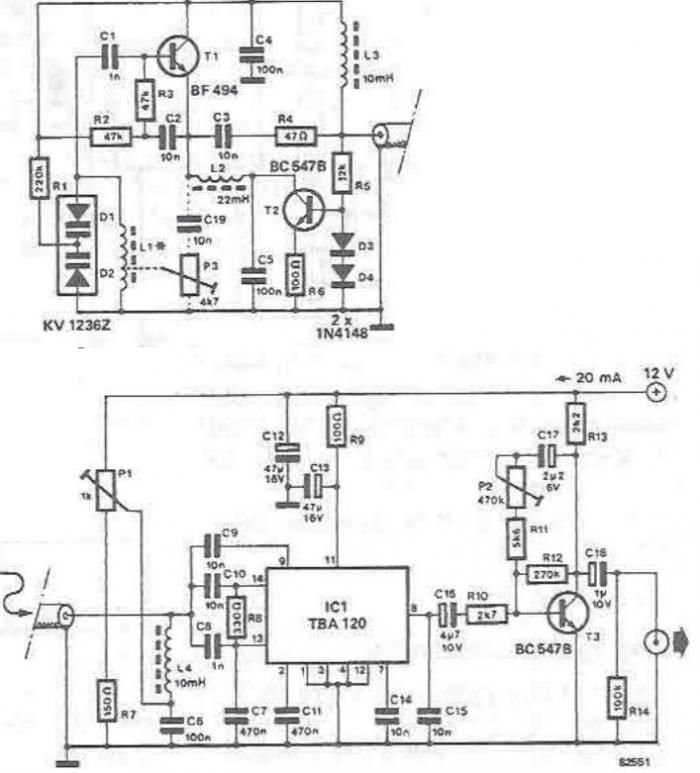
This amplifier has good efficiency and low current consumption while the quiet sounds and pauses of the signal, this allows to store the energy of the carrier and use the energy at the peaks of the audio signals. The circuit diagram of the receiver with the amplifier based on the push-pull emitter follower is shown in Fig.
1. The AC component of the detected signal passes through the coupling capacitors C3, C4 to the bases of transistor amplifier, and the DC component passes through the choke L2 to the storage capacitor C5. This capacitor cannot be directly connected to the detector because in this case the audio signal will be smoothed and suppressed.
The parameters of the choke are not critical, so you can use any choke or any transformer with a winding, containing not less than 2000 turns wound on the magnetic core with cross section not less than 1 cm2. The optimal transformation ratio of the transformer T1 is about 30 for the load of 4 ohms. It is convenient to use a small power supply transformers from transistor radios with the voltage ratio 220 V to 6.
5. 9 V. A suitable output audio transformer can be used too. The large size of the device (due to the heavy transformer and choke) is not an issue, because it uses the large antenna and a floor standing speaker system, so this is not a portable radio! The use of a voltage doubling rectifier allows to increase the supply voltage of the circuit. Distortion on peaks of signal will be decreased. A bridge amp 🔗 External reference
Related Circuits
The transmitter operating at 2 meters (144 MHz) was primarily designed for use by radio amateurs as a radio beacon. It generates a high-quality signal suitable for this purpose. The 2-meter transmitter circuit typically includes several key components to ensure...
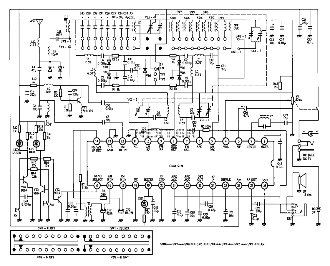
Desheng 1012 is a 12-band radio circuit diagram that covers FM, MW, SW, and TV sound frequencies. The Desheng 1012 radio circuit is designed to receive a wide range of frequencies across multiple bands, including FM (Frequency Modulation), MW...
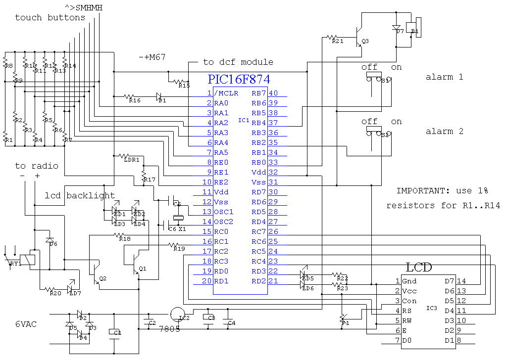
The program utilizes the built-in analog-to-digital (AD) converter of the PIC16F874 microcontroller for sensing touch buttons. The PIC features eight AD ports, with seven designated for the touch buttons and one for light measurement. To receive DCF signals, a...
The tuning stage of this long-wave and medium-wave radio receiver also functions as an active antenna, which can be optimally positioned for the best reception. The circuit is completely independent from the receiver, which includes a demodulator that provides...
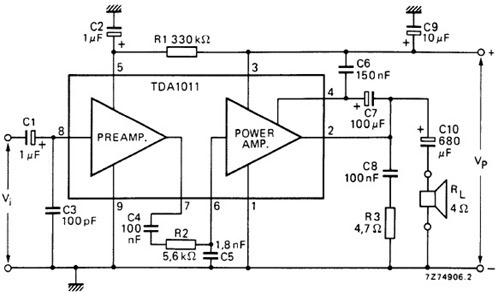
The following schematic illustrates the design of a 4 Watt Amplifier Circuit Diagram intended for portable radio applications, utilizing the TDA1011 integrated circuit from Philips Semiconductor. The 4 Watt Amplifier Circuit is designed to provide audio amplification in portable radio...
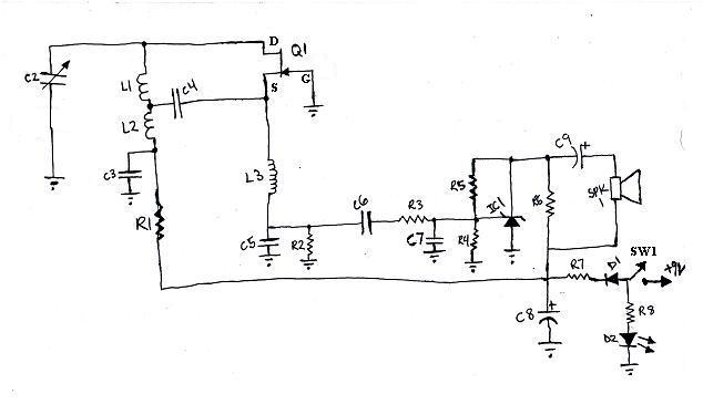
L1 and L2 were constructed by wrapping three tight loops side by side around a Sharpie marker. L2 was additionally created by wrapping approximately 8 inches of 35 AWG magnet wire around a ferrite core, ensuring that the windings...