
Radio Glen TBU
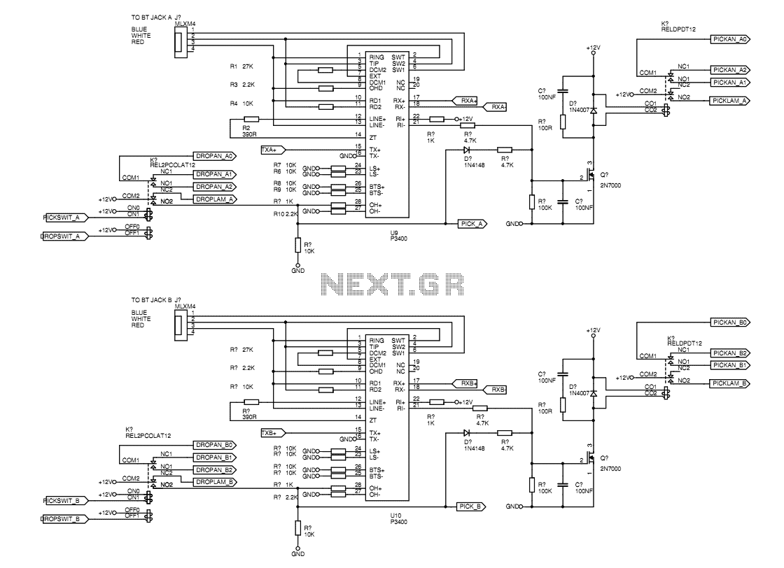
The ETAL P3400 line modules serve as the primary components in the circuit, effectively managing the telephone line interface functions necessary for proper operation. The circuit includes differential amplifiers on both the RX and TX sides of the hybrid. The RX side receives incoming signals, while the TX side transmits signals from the studio mixer to the phone line. The design incorporates bandpass filters to ensure that the transmitted audio signals remain within the defined frequency range, specifically between 200Hz and 3500Hz, thereby optimizing the audio quality and minimizing crosstalk.
Crosstalk, an inherent issue in hybrid circuits, occurs when the TX signal leaks into the RX signal path. To mitigate this, the circuit employs a cancellation technique where the TX signal is subtracted from the RX signal. This process is enhanced by introducing a phase shift to align the TX signal accurately with the crosstalk. Adjustable preset potentiometers are utilized for fine-tuning both the amplitude and phase of the cancellation signal, allowing for precise control during setup.
The adjustment procedure requires the TBU to be in an active call state, with a test signal (1KHz sine wave) injected into the TX path. The RX signal is then monitored using an oscilloscope, enabling the operator to adjust the pots for optimal crosstalk reduction. Although adjustments are recommended during actual operation, it has been observed that variations in phone lines generally do not necessitate frequent recalibrations.
The output from the cancellation circuitry is subsequently processed through a second bandpass filter, ensuring that unwanted frequencies outside the telephone bandwidth are attenuated. This stage is critical for maintaining audio integrity and preventing interference from hum or high-frequency noise.
A differential driver output is included to provide a balanced signal suitable for connection to the studio mixer. While the driver performs well with high-impedance inputs, it may face challenges when interfaced with a true 600-ohm balanced load. To further enhance system reliability, the DG444 analogue switch is integrated into the design. This switch disconnects the RX signal when the TBU is in the on-hook state, preventing potential feedback issues between the TX and RX paths.
Overall, the circuit design effectively addresses the common challenges associated with telephone line interfacing, ensuring high-quality audio transmission while minimizing the negative effects of crosstalk and interference.The heart(s) of the unit are the ETAL P3400 line modules available from Farnell. These modules mop-up all of the line interface functions like ring detection, physical hybrid, on-off hook handling etc. This means that the TBU as a whole would probably pass PSTN type approval testing if it was subjected to it.
This sheet shows the differential amplifiers which take the signal from the RX side of the hybrid, and the differential amps which accept the mixer TX output for sending to the TX side of the hybrid. The TX signal is bandpass filtered with -3dB points of 200Hz and 3500Hz at -12dB/octave. This avoids sending unecessarily wide audio to the telephone line and makes cancellation of the TX crosstalk easier.
RX refers to the signal being received from the far end of the phone line and sent to the studio mixer. TX refers to the signal going from the studio mixer to the phone line. Because of the imperfect nature of hybrids and phone lines, the RX signal typically has a roughly equal amount of the TX signal present due to crosstalk.
This TX crosstalk is cancelled by subtracting the known TX signal from the RX signal. Measurements have shown that the TX crosstalk signal coming out of the RX side of the hybrid is also slightly phase shifted from the original TX signal. So an equivalent phase shift is added to the signal that is used to cancel the TX crosstalk signal. The cancellation amplitude and phase shift are adjustable on preset pots. To adjust these pots, the TBU has to be put into a call. The receiver of the phone that is dialled up may be simply left on a cushion to block the mouthpiece.
A 1KHz sine is sent to the TX from the mixer and the amount of this sine on the RX is measured with an oscilloscope. The amplitude pot is adjusted first, to minimise the level of the crosstalk signal. Then the phase pot is adjusted to minimise the crosstalk signal. There is not much interaction between the two pots but it may be of benefit to readjust the amplitude pot and then the phase pot again.
This adjustment should ideally be done when the TBU is connected to the actual line to be used in the field. In practice however, the difference between phone lines has a minimal impact and no adjustment should be needed.
The RX signal from the cancellation circuitry is passed on to a bandpass filter which rolls off at 12dB/octave with -3dB fo at 200Hz and 3500Hz. This provides for the full available telephone bandwidth while providing some cut-off of hum and high frequency noise that may be present.
A differential driver output provides the balanced signal for the studio mixer. This output can drive an ordinary high impedance balanced input but will struggle if a true 600R balanced load is applied. The DG444 analogue switch cuts off the RX signal to the mixer when the TBU is on-hook. This cut-off of the RX audio prevents a feedback path from TX to RX which can occur when in the on-hook state.
The switch drive signal is effectively 12V logic and comes from the latching relay which controls the hook state. 🔗 External reference
Related Circuits
If familiar with programming languages such as C++, PASCAL, VISUAL BASIC, or DELPHI, it is possible to write a program that sends numbers from 0 to 255 through the parallel port (378 I) of a PC. This process checks...

Superheterodyne receivers have been mass-produced since around 1924, but for reasons of cost did not become successful until the 1930s. Superheterodyne receivers represent a pivotal advancement in radio technology, characterized by their ability to convert high-frequency signals into lower...
The source connection is tapped into the tuning coil low down, as a means of impedance matching with the headphones and acts as the anode, while the drain connects with your headphones as the cathode, to complete the detector...
Superheterodyne receivers have been mass-produced since around 1924, but for reasons of cost did not become successful until the 1930s. Before World War II, other, simpler receiver technologies such as the TRF receiver and the regenerative receiver were still...
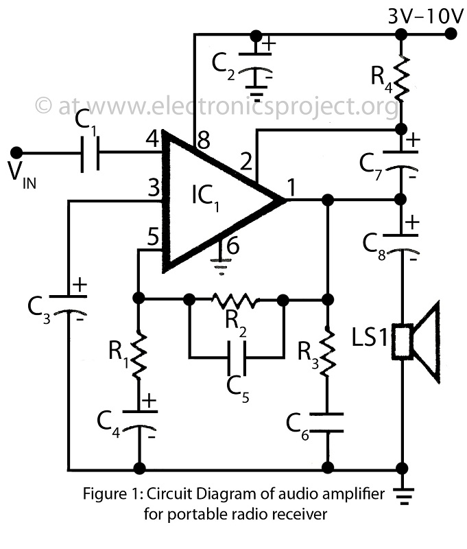
This is a simple audio amplifier circuit built around the BEL1895 1W audio amplifier integrated circuit (IC). This circuit serves as an alternative to more complex audio amplifier circuits designed for portable radio receivers. It does not require a...
This crystal set has been designed to incorporate features from previous radio models. The #62 radio merges the single-piece design of the #48 set with the dual detector functionality of more recent models. It utilizes a dual honeycomb coil...
Warning: include(partials/cookie-banner.php): Failed to open stream: Permission denied in /var/www/html/nextgr/view-circuit.php on line 713
Warning: include(): Failed opening 'partials/cookie-banner.php' for inclusion (include_path='.:/usr/share/php') in /var/www/html/nextgr/view-circuit.php on line 713