
Tuned Radio Frequency (TRF) Receiver
Superheterodyne receivers represent a pivotal advancement in radio technology, characterized by their ability to convert high-frequency signals into lower intermediate frequencies (IF) for easier processing. The fundamental operation of a superheterodyne receiver involves mixing the incoming radio frequency (RF) signal with a locally generated oscillator signal to produce the IF. This process allows for improved selectivity and sensitivity, as the IF can be amplified and filtered more effectively than the original RF signal.
The architecture of a typical superheterodyne receiver includes several key components: an antenna, a radio frequency amplifier, a mixer, a local oscillator, an intermediate frequency amplifier, and a demodulator. The antenna captures the RF signals, which are then amplified by the RF amplifier to enhance the signal strength. The mixer combines the amplified RF signal with the output from the local oscillator, creating the IF signal, which is usually at a fixed frequency, allowing for uniform processing of various RF inputs.
The local oscillator is crucial as it determines the frequency to which the incoming signal will be shifted. This frequency can be adjusted to tune into different stations. The IF amplifier further boosts the IF signal, improving the signal-to-noise ratio before it is demodulated to retrieve the original audio or data content.
Superheterodyne receivers are widely used in various applications, including AM and FM radio, television, and two-way communication systems. Their ability to handle a wide range of frequencies and provide high-quality reception makes them a popular choice in modern electronic communication systems. The evolution of superheterodyne technology has led to the development of more sophisticated designs, incorporating digital signal processing techniques to enhance performance and functionality.Superheterodyne receivers have been mass-produced since around 1924, but for reasons of cost did not become successful until the 1930s. Before the second.. 🔗 External reference
Related Circuits
The TDA7088T can be used in mono portable and pocket radios. This is a bipolar integrated circuit. Here is one of the application circuit diagrams. The TDA7088T is a versatile bipolar integrated circuit designed specifically for mono FM radio applications,...
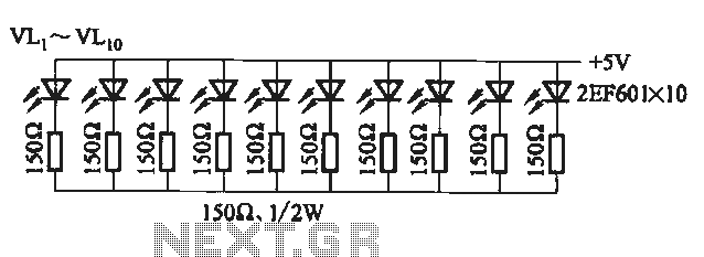
This set of two circuits forms the basis for a simple light wave transmitter. A laser beam is modulated and directed towards a receiver that demodulates the signal and presents the information, such as voice or data. The assembly...
When a DC voltage signal is transmitted over long distances, it experiences attenuation with unpredictable characteristics introduced by the transmission medium, such as cable resistance that varies with temperature changes. In contrast, carrying information using frequency rather than a...
The circuit utilizes a 555 timer configured as a multivibrator, where the oscillation frequency is determined by resistors R1, R2, and capacitor C1. The frequency formula is given by fo = 1.443 / ((R1 + R2) * C1). The...
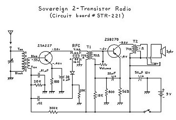
An analysis of certain radios reveals the impressive engineering by Japanese designers, particularly in creating a radio capable of driving a speaker with only two transistors. The first transistor (Q1) serves a dual function; it operates as an RF...
This document outlines modifications made to the RIG RX-2 receiver, enabling remote control via a computer using an RS-232 serial interface. The modifications consist of two components: additional hardware and a new firmware program for the PIC16C84 microcontroller. In...