
Tuned Radio Frequency (TRF) Receiver
 Receiver")
The superheterodyne receiver described is a notable example of a circuit that combines traditional techniques with modern enhancements to achieve effective radio reception. The design utilizes six transistors, strategically configured to maximize performance while maintaining simplicity. The input stage, which employs positive feedback, is crucial for enhancing both sensitivity and selectivity, allowing the receiver to discern signals from various stations effectively.
The circuit's architecture begins with a selective amplifier, which is finely tuned to operate just below the oscillation threshold. This careful adjustment is critical, as it enhances gain and narrows bandwidth, improving the receiver's ability to isolate desired frequencies. A potentiometer connected to the drain of a Field-Effect Transistor (FET) allows for precise tuning. Users must adjust this component with care to ensure optimal performance, as the quality of reception is directly tied to this setting.
The receiver is designed to operate within the frequency range of 6 MHz to 8 MHz, making it suitable for receiving broadcasts from the 49 m and 41 m shortwave bands, which are commonly utilized by numerous European radio stations. The inclusion of a 50 cm antenna should provide satisfactory reception during daylight hours, while nighttime conditions may yield even better results, allowing for the reception of multiple strong stations.
Following the initial amplification stage, the signal is fed into a transistor detector, which demodulates the incoming radio signals. This is followed by two low-frequency amplifier stages that enhance the audio output. The final output stage employs a push-pull configuration, which is particularly effective for driving low-impedance loudspeakers, ensuring that the audio signal is delivered with sufficient power and clarity.
Setting up the receiver is designed to be user-friendly. The adjustment of potentiometer P1 is the initial step, where the user should turn it until an audible whistle indicates that the circuit is on the verge of oscillation. The user then reduces the setting until the whistle ceases, allowing for the tuning of the receiver to a specific broadcast station. It is common for additional minor adjustments to be necessary once a station is locked in, ensuring continued optimal performance.
The receiver is powered by a supply voltage that ranges from 5 V to 12 V, making it versatile for various power sources. Its low current consumption is an advantage, especially when using a 9 V PP3 (6F22) battery, which provides extended operational life, making this design not only effective but also efficient for practical use in everyday applications.Superheterodyne receivers have been mass-produced since around 1924, but for reasons of cost did not become successful until the 1930s. Before the second world war other, simpler receiver technologies such as the TRF receiver and the regenerative receiver were still widespread.
The circuit described here is based on the old technology, but brought up-to-date a The most important part of the circuit is the input stage, where positive feedback is used to achieve good sensitivity and selectivity. The first stage is adjusted so that it is not quite at the point of oscillation. This increases the gain and the selectivity, giving a narrow bandwidth. To achieve this, the potentiometer connected to the drain of the FET must be adjusted very carefully: optimal performance of the receiver depends on its setting.
In ideal conditions several strong stations should be obtainable during the day using a 50 cm antenna. At night, several times this number should be obtainable. The frequency range of the receiver runs from 6 MHz to 8 MHz. This range covers the 49 m and the 41 m shortwave bands in which many European stations broadcast. Not bad for such a simple circuit! The circuit employs six transistors. The first stage is a selective amplifier, followed by a transistor detector. Two low-frequency amplifier stages complete the circuit. The final stage is a push-pull arrangement for optimal drive of the low-impedance loudspeaker. This circuit arrangement is sometimes called a 1V2 receiver` (one preamplifier, one detector and two audio-frequency stages).
Setting-up is straightforward. Adjust P1 until the point is reached where the circuit starts to oscillate: a whistle will be heard from the loudspeaker. Now back off the potentiometer until the whistle stops. The receiver can now be tuned to a broadcaster. Occasional further adjustment of the potentiometer may be required after the station is tuned in. The receiver operates from a supply voltage of between 5 V and 12 V and uses very little current. A 9 V PP3 (6F22) battery should give a very long life. 🔗 External reference
Related Circuits
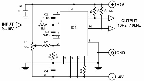
A voltage-to-frequency converter with a control range of 1:1000 can be constructed using the IC TSC9402. The specified component values in the circuit yield a conversion factor of 1 kHz per 1 V. Input voltages ranging from 10 mV...
A 0 to 2 MHz frequency meter with a Minimum Mass Wireless Coupler, based on the ATMega8. Range to the Minimum Mass Base Unit is 10 to 15 cm. Since the frequency meter is battery operated, it can be...
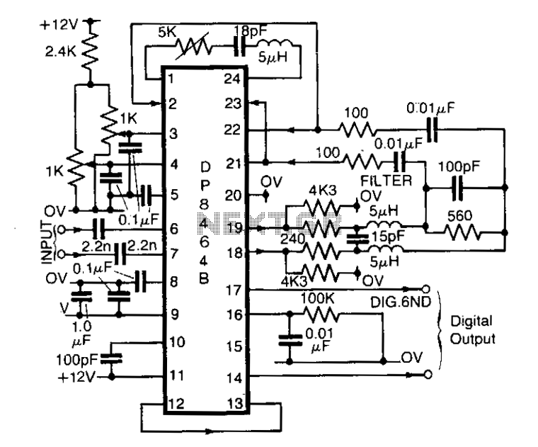
The DP8464B from National Semiconductor is designed primarily for use in disk systems as a pulse detector. However, it can also function effectively as a general-purpose peak detector for analog signals up to 5 MHz. This integrated circuit can...
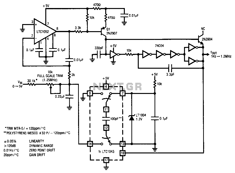
This stabilized voltage-to-frequency converter operates within a range of 1 Hz to 1.25 MHz, featuring a linearity of 0.05% and a typical temperature coefficient of 20 ppm/°C. The circuit is powered by a single 5-V supply. It employs a...
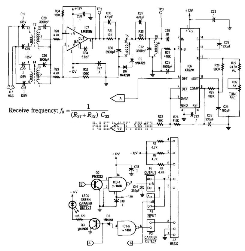
This receiver consists of an input network, amplifier IC7, FSK PLL detector IC8, and output amplifier/interface circuits Q2, Q3, IC3A, and IC3B, which include a 1488 Quad RS232 line driver for the carrier-current signal. The tuned amplifier IC7 amplifies...
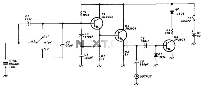
This circuit utilizes a Colpitts oscillator (Q1) paired with a buffer amplifier (Q2) to facilitate crystal testing. SI allows for the selection of three load conditions: series (S), 20 pF, and 32 pF. It is essential to keep the...