
radio if

The interface circuit is designed to facilitate seamless communication between a radio transceiver and a personal computer, enhancing functionality for amateur radio operators. The integration of optocouplers ensures that digital control signals are electrically isolated from the radio, protecting both devices from potential damage due to ground loops or voltage spikes. The use of audio transformers serves to maintain signal integrity while isolating audio paths, which is critical for high-fidelity audio transmission and reception, especially in digital modes where signal clarity is paramount.
Operational amplifiers play a crucial role in signal amplification, allowing for appropriate signal levels to be maintained throughout the communication chain. The design's flexibility in adjusting gain via resistors offers users the ability to tailor the interface to their specific equipment and operational preferences, ensuring optimal performance across different radios and sound cards.
The inclusion of a voltage regulator allows for versatile power supply options, accommodating various operating environments and setups. The thoughtful layout of connectors and controls on the interface box enhances user experience, providing intuitive access to essential functions while minimizing the risk of connection errors.
Overall, this interface box represents a well-engineered solution for connecting radios to PCs, combining essential features with robust design principles for reliable operation in various amateur radio applications.This is a simple interface box to allow connecting a radio to a PC with some improvements with respect to similar projects available almost everywhere. Interfaces like this one are used to manage via PC the transmission and reception of digital signals (RTTY, BPSK and other digital modes) and of CW (morse) signals (using skimmers to decode them).
I also use this interface to record on the PC my QSOs in particular during contests. A gain control is provided both on the Rx chain and Tx chain to allow to adapt this interface to any kind of radio, providing a constant impedance on the audio lines, on both PC and radio sides. The reson why I realised this board and I did not choose one of those available on the market is mainly for the two above mentioned reasons.
Having a goog galvanic isolation between PC and radio is fundamental, to avoid ground-loops which may introduce noise in the receiver and at the same time this will protect both the radio and the PC. Just to make an example, I had a PC sound-card damaged probably by a too high current on its output line (probably the impedance on the radio side was too low).
The possibility to adjust the audio levels to fit with the radio and PC is important. In this way I can avoid distorsions that may compromise the transmission and reception, in particular when using AFSK. Obviously, you can buy a digital interface like one of those produced by microHAM. This kind of interfaces will give you much more functionalities, but the category of price is much different and from my point of view, a good PC sound-card works fine (or at least you can get reasonable performances).
The connection between the PC and the radio is performed via one serial port which manage the PTT and RTTY/CW signals and via "line in" and "line out" ports of the PC sound-card. Parallel port can be also used as an alternative to the serial port, in case needed. Probably all SW for contesting and for digital modes handle both ports, but the newest PC will provide only serial port and in some cases only USB ports are now available.
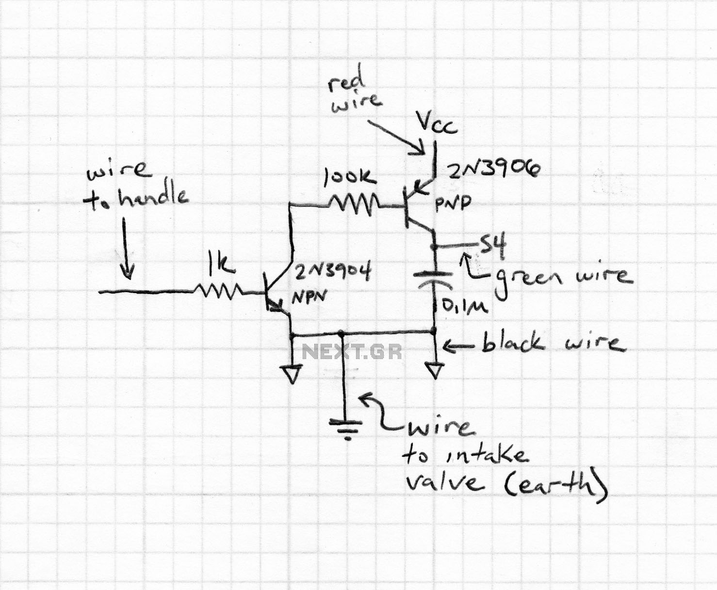
In the last case a USB-to-RS232 adapter can be bought at very low cost. This is the electrical diagram of the circuit. The insulation of the PTT and RTTY signals are obtained via two optocoupler 4N35 while the two audio signals (in and out) are insulated with two audio 1:1 transformers. Two op-amp (LM358) are used to amplifiy the in and out signals and to provide the constant impedance at the input and output ports of about 1kOhm.
The audio level can be adjusted by mean of the two potentiomenters, but I preferred to set a fixed gain on the two op-amp. This gain can be adjusted changing the value of R1 and R3 to fit with the radio in/out levels (it should be set to have a maximum signal level just a bit higher than the value expected by the sound-card and by the radio).
The circuit also include a voltage regulator to allow supply it directly with a 12V AC transformer. I preferred to use this solution to avoid ground-loops with the radio 12V supply line. In case you want you can also supply the circuit using the radio 12V stabilised supply. The assembled board and my interface box can be seen below. I put on the front panel the ON/OFF switch, three leds (ON/OFF, RTTY and PTT) and a DIN connector for the radio interface (this will allow to connect the cable of each radio I have). On the back-side I used a CANON 9-PIN connector to interface with the PC. I used a signle shielded cable for all signals. RS-232 and audio lines are split inside the RS-232 connector on the PC side, as you can see in picture below).
In case yuo want to realise your interface I have still some PCBs available (as shown in picture above). The transformer I used can be bought on-line on the RS Components site. Its order code is. You can find it directly here. I have also few available. 🔗 External reference
Related Circuits
Most surviving TR-1 radios no longer function. Many collectors prefer to maintain them in their original condition to preserve authenticity. However, there may come a time when one wishes to hear the radio play. Before proceeding with any modifications,...
The FM radio receiver with PLL designed by A. Zaharov continues to attract the interest of radio amateurs. According to a publication in the magazine "Radio," one of the primary drawbacks of this type of detector is its low...
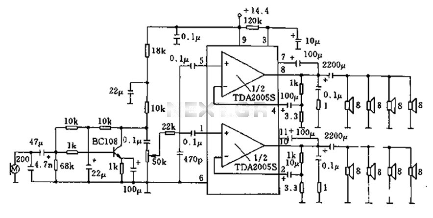
20W bus radio and megaphone circuit utilizing the TDA2005S double low-frequency power amplifier integrated circuit design. The front end can be connected to either a microphone input or a low-frequency radio output voltage amplification stage. Each TDA2005S provides 10W...
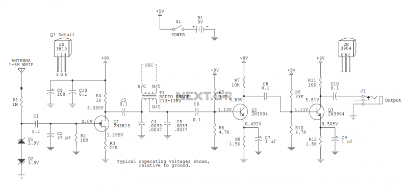
This version sports a 2nd audio amplifier stage at Q3. The output level with this version is sufficient to drive a crystal headphone to a comfortable volume. The "crystal" headphone is like those used on ye olde crystal radios....
Here is the schematic diagram for a very basic crystal radio set without any particular embellishments. This basic old time radio uses no power other than that provided by the transmitting antenna from the radio station. Free power from...
The TPTG transmitter has been transformed into a modern TNT model. This transmitter can utilize the existing K-111 power pack for both the transmitter and receiver, eliminating the need for a separate power supply unit. Building this compact transmitter...