
radio remote control
The remote control unit circuit operates on the principle of using radio frequency signals to transmit control commands to various electrical devices. This design is particularly advantageous as it circumvents the limitations of infrared-based systems, providing a broader range of operation. The DTMF signals serve as a robust method for encoding commands, allowing for multiple channel configurations.
The transmitter section utilizes the UM91214B IC, which is responsible for generating the DTMF tones. The output from this IC is frequency-modulated using an FM transmitter circuit, which is tuned to a specific carrier frequency determined by the coil and adjustable capacitor. The antenna's length is optimized to ensure effective signal propagation, and the metal enclosure for the transmitter mitigates potential interference from external electromagnetic fields.
In the receiver section, the FM receiver is tasked with demodulating the incoming signals and extracting the DTMF tones. The KT3170 IC, functioning as the DTMF-to-BCD converter, translates these tones into binary-coded decimal outputs that correspond to the pressed buttons on the transmitter. This output is then utilized to toggle flip-flops, which are configured to control relays that manage the electrical appliances.
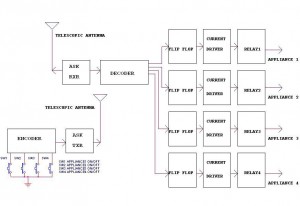
The ability to expand the circuit to 12 channels introduces flexibility for users who may want to control multiple devices. This is achieved by incorporating a demultiplexer, which allows for the distribution of the DTMF signals to additional flip-flops, thus facilitating the control of more appliances without significant redesign of the existing circuit architecture. Overall, this remote control unit demonstrates an effective integration of DTMF technology with radio frequency transmission, creating a versatile solution for remote management of electrical systems.Circuit Here is a circuit of a remote control unit which makes use of the radio frequency signals to control various electrical appliances. This remote control unit has 4 channels which can be easily extended to 12. This circuit differs from similar circuits in view of its simplicity and a totally different concept of generating the control signal
s. Usually remote control circuits make use of infrared light to transmit control signals. Their use is thus limited to a very confined area and line-of-sight. However, this circuit makes use of radio frequency to transmit the control signals and hence it can be used for control from almost anywhere in the house. Here we make use of DTMF (dual-tone multi frequency) signals (used in telephones to dial the digits) as the control codes.
The DTMF tones are used for frequency modulation of the carrier. At the receiver unit, these frequency modulated signals are intercepted to obtain DTMF tones at the speaker terminals. This DTMF signal is connected to a DTMF-to-BCD converter whose BCD output is used to switch-on and switch-off various electrical applicances (4 in this case).
The remote control transmitter consists of DTMF generator and an FM transmitter circuit. For generating the DTMF frequencies, a dedicated IC UM91214B (which is used as a dialler IC in telephone instruments) is used here. This IC requires 3 volts for its operation. This is provided by a simple zener diode voltage regulator which converts 9 volts into 3 volts for use by this IC.
For its time base, it requires a quartz crystal of 3. 58 MHz which is easily available from electronic component shops. Pins 1 and 2 are used as chip select and DTMF mode select pins respectively. When the row and column pins (12 and 15) are shorted to each other, DTMF tones corresponding to digit 1 are output from its pin 7. Similarly, pins 13, 16 and 17 are additionally required to dial digits 2, 4 and 8. Rest of the pins of this IC may be left as they are. The output of IC1 is given to the input of this transmitter circuit which effectively frequency modulates the carrier and transmits it in the air.
The carrier frequency is determined by coil L1 and trimmer capacitor VC1 (which may be adjusted for around 100MHz operation). An antenna of 10 to 15 cms (4 to 6 inches) length will be sufficient to provide adequate range. The antenna is also necessary because the transmitter unit has to be housed in a metallic cabinet to protect the frequency drift caused due to stray EM fields.
Four key switches (DPST push-to-on spring loaded) are required to transmit the desired DTMF tones. The switches when pressed generate the specific tone pairs as well as provide power to the transmitter circuit simultaneously. This way when the transmitter unit is not in use it consumes no power at all and the battery lasts much longer.
The receiver unit consists of an FM receiver (these days simple and inexpensive FM kits are readily available in the market which work exceptionally well), a DTMF-to-BCD converter and a flip-flop toggling latch section. The frequency modulated DTMF signals are received by the FM receiver and the output (DTMF tones) are fed to the dedicated IC KT3170 which is a DTMF-to-BCD converter.
This IC when fed with the DTMF tones gives corresponding BCD output; for example, when digit 1 is pressed, the output is 0001 and when digit 4 is pressed the output is 0100. This IC also requires a 3. 58MHz crystal for its operation. The tone input is connected to its pin 2 and the BCD outputs are taken from pins 11 to 14 respectively.
These outputs are fed to 4 individual ½D ½ flip-flop latches which have been converted into toggle flip-flops built around two CD4013B ICs. Whenever a digit is pressed, the receiver decodes it and gives a clock pulse which is used to toggle the corresponding flip-flop to the alternate state.
The flip-flop output is used to drive a relay which in turn can latch or unlatch any electrical appliance. We can upgrade the circuit to control as many as 12 channels since IC UM91214B can generates 12 DTMF tones.
For this purpose some modification has to be done in receiver unit and also in between IC2 and toggle flip-flop section in the receiver. A 4-to-16 lines demultiplexer (IC 74154) has to be used and the number of toggle flip-flops have also to be increased to 12 from the existing 4
🔗 External reference
Related Circuits
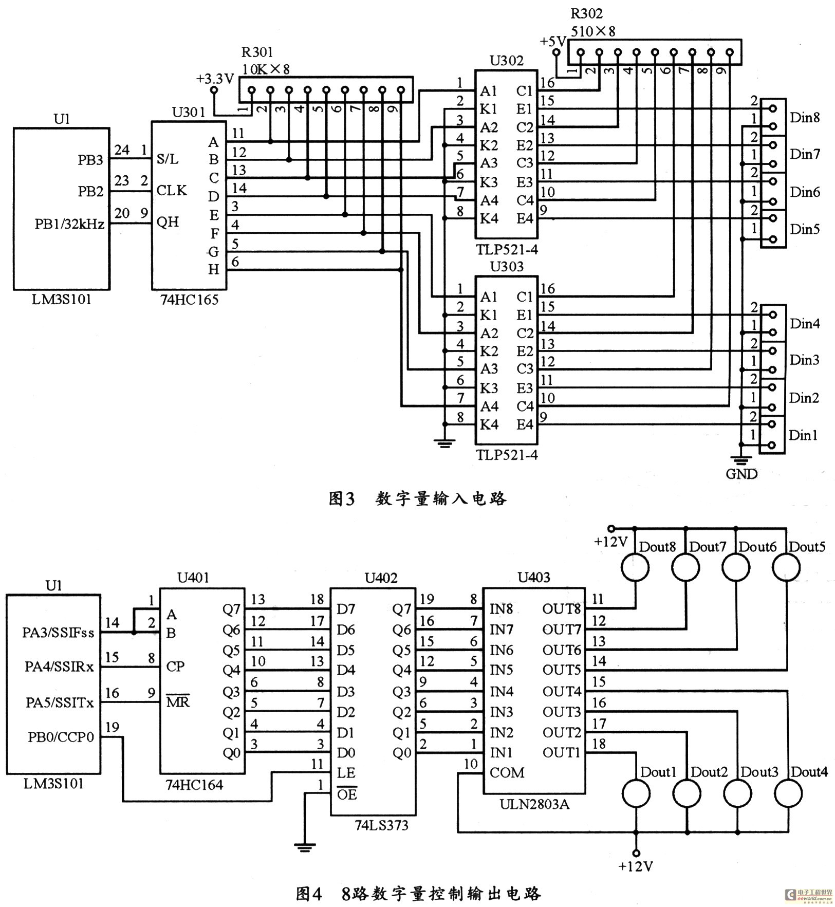
The figure utilizes a controller as the primary equipment for gathering and controlling digital data within an on-site monitoring system. The stability of on-site control operations is crucial to the overall system performance. Therefore, a simple and stable structure...
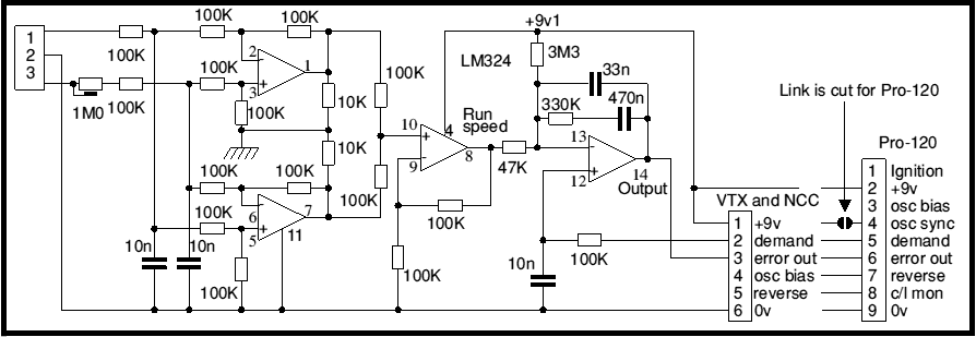
Most battery motor speed controllers are under manual control and the operator automatically adjusts speed to match demand. Under these conditions closed loop motor speed control is an unnecessary expense. However, when it is required, a tachogenerator can easily...
This circuit illustrates a remote control circuit diagram using RF technology without the use of a microcontroller. Features include a simple remote control circuit that operates via radio frequency. The remote control circuit operates by transmitting signals through radio waves,...
An FM radio generates an interference signal that can be detected on another FM radio tuned 10.7 MHz higher than the original. A 50 kΩ potentiometer is used to adjust the modulation level to its maximum without introducing distortion....
The automatic irrigation control circuit is designed to manage crop irrigation based on soil moisture levels. It is applicable in various agricultural settings, including state farms, orchards, vegetable greenhouses, and large farmland areas. The circuit comprises a soil moisture...
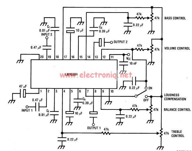
This volume controller equalizer electronic project is designed using the LM1036 DC tone volume controller, featuring a volume and balance circuit for stereo applications. The four control inputs of the LM1036 volume controller enable the control of bass, treble,...