
Remote ControlCircuit Through RF Without Microcontroller

The remote control circuit operates by transmitting signals through radio waves, enabling wireless communication between the transmitter and receiver. The system typically comprises two main components: the transmitter circuit and the receiver circuit.
The transmitter circuit is designed to generate radio frequency signals. It usually includes a simple oscillator circuit, which can be built using components such as a 555 timer IC or a transistor-based oscillator. The oscillator creates a modulated signal that represents the control commands. A radio frequency (RF) module, such as an RF transmitter, is used to broadcast these signals. The choice of frequency is critical, as it must comply with local regulations and avoid interference with other devices.
On the receiving end, the receiver circuit consists of an RF receiver module that captures the transmitted signals. This module demodulates the received signal and converts it back into a usable form. The demodulated signal can then be processed to control various devices, such as motors, lights, or other electronic components. Additional components such as amplifiers and filters may be included to enhance signal integrity and reduce noise.
Power supply considerations are also important for both the transmitter and receiver circuits. Typically, battery-operated systems are used for portability, while ensuring that the power requirements of all components are met.
Overall, this remote control circuit design is valued for its simplicity and effectiveness in enabling wireless control without the complexity of a microcontroller, making it suitable for various applications in hobbyist projects and basic automation tasks.This circuit shows about Remote Control Circuit Diagram Through RF Without Microcontroller . Features: simple remote control circuit, uses radio . 🔗 External reference
Related Circuits
In the present day, a wide variety of sensors are available to measure almost anything. This tutorial will explore the fascinating world of sensors, starting with a very simple analog temperature sensor, the LM35. The process of interfacing it...
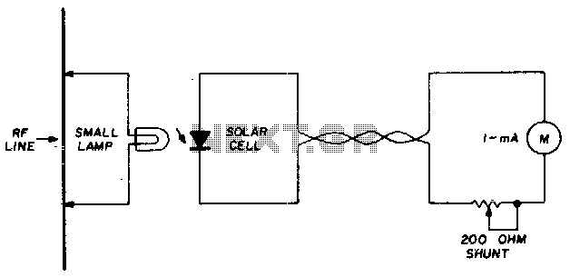
A suitable pilot lamp is illuminated by a small sample of RF energy and energizes an inexpensive solar cell; the DC current generated by the cell serves as a measure of relative RF power and may be routed to...
The hardware is constructed from two modules, one to capture the signal and provide timing functions, and the second as transmitter placed somewhere near the target equipment. It has been interfaced with an IBM compatible PC on the printer...
If the sensor system requires an active supply, a single pair of cables can be utilized to transmit both the power supply and the output signal. This approach simplifies the overall system. In sensor systems that necessitate an active power...
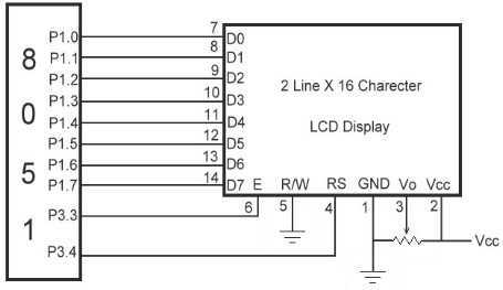
The link shows how to interface Alphanumeric LCD to 8051 Microcontroller. Liquid Crystal Display also called as LCD is very helpful in providing user interface as well as for debugging purpose. The most common type of LCD controller is...
This section describes an experimental low power, low bandwidth data signaling system that was initially made to operate at 55 MHz (television channel 2 in the U.S.). Before operating a radio transmitter, find out what kind of transmitter operation,...