
Motor speed controller using LM324

To put that more simply: the feedback system must alter the output voltage to the motor so that the motor voltage is raised to exactly match the drop in the motor armature caused by the current flowing, so the mechanical speed remains constant.
If the loop over compensates, then the motor will go too fast if loaded and will 'hunt' - the speed will be unstable and will bounce about. If the compensation is too little - performance will be less than optimum.
However - there are a lot of variables, including battery voltage and motor temperature. An ideal system would measure everything and compensate for it (and be very expensive!). In practice, adjustment is quite easy: you will simply include a pot in series with the motor used as the tacho generator and will adjust this until the motor starts to hunt (show speed variation), then back it off a bit until it is slightly below optimum. The board is built in two versions (Pro-120 and VTX or NCC) but the only difference is the connector - 9 way for Pro (black numbers) and 6 way for VTX.
The circuit uses a quad op-amp type LM324. The first two stages are straightforward difference amplifiers that compare the two wires from the tacho generator. One works for positive voltages and the other for negative.
Now the circuit is used from a single supply. Therefore the op-amp outputs cannot swing negative. Therefore one amplifier gives a positive output for one tacho generator direction and the other for the reverse direction. The third section of the op-amp sums the outputs, the result is a rectified version of the input.
There is a snag in using an op-amp thus. On the inputs which should swing the output negative, the op-amp is in fact cut-off and the output is not conducting. The inputs are outside their working range, so they cannot clamp the control signal. There is then a straight feed-forward path via the 'feedback' resistor to the inoperative output.
That mechanism explains the 10K load resistors from the outputs of the first two stages of the op-amp to earth. These, in conjunction with the three 100K resistors in the feed-forward path, form an attenuator so that the error from feed-forward is reduced to around 3%. It may interest browsers to know that the circuit was first used with an LM3900 (which is a Norton op-amp) where the inputs can never rise above one transistor Vbe above 0V. With this, the feed-forward effect is not noticeable and the clamping resistors are not required. The LM3900 circuit which you will note, does not show an output integrator.
The fourth stage compares the rectified tacho generator voltage with the demand speed, integrates the difference, and gives an output to drive the PWM modulator.
The feedback system is critical in maintaining stable motor speed under varying load conditions. The loop gain must be carefully managed to avoid instability, which can result in oscillations or hunting behavior. The operational amplifier configuration allows for differentiation between the positive and negative voltage outputs from the tacho generator, enabling effective feedback control.
In practical applications, a potentiometer is often used to fine-tune the system, allowing for adjustments based on real-time operational conditions. The integration stage in the circuit serves to filter out any DC offset from the error signal, ensuring that the PWM modulator receives a clean control signal for precise motor speed regulation.
The overall design emphasizes simplicity and cost-effectiveness, utilizing readily available components while still achieving the desired closed-loop control performance. The use of the LM324 op-amp in this application highlights the adaptability of common ICs in creating robust motor control solutions.Most battery motor speed controllers are under manual control and the operator automatically adjusts speed to match demand. Under these conditions closed loop motor speed control is an unnecessary expense. However, when it is required, a tachogenerator can easily be added. True tachogenerators are usually expensive - which puts off most potential users. The expense is because they are very accurately manufactured and calibrated. They are also low volume items. However for most uses a small permanent magnet motor is perfectly adequate. It won't come with an accurate 'volts per rpm' calibration and it may (just possibly) drift over several years.
For most purposes this simply does not matter! With any tacho feedback system, the loop gain (controller, motor, tacho, tacho amplifier) must not be more than unity or instability results. To put that more simply: the feedback system must alter the output voltage to the motor so that the motor voltage is raised to exactly match the drop in the motor armature caused by the current flowing, so the mechanical speed remains constant.
If the loop over compensates, then the motor will go too fast if loaded and will 'hunt' - the speed will be unstable and will bounce about. If the compensation is too little - perfornance will be less than optimum. However - there are a lot of variables, including battery voltage and motor temperature. An ideal system would measure everything and compensate for it (and be very expensive!). In practise, adjustment is quite easy: you will simply include a pot in series with the motor used as the tacho generator and will adjust this until the motor starts to hunt (show speed variation), then back it of a bit until it is slightly below optimum.
The board is built in two versions (Pro-120 and VTX or NCC) but the only difference is the connector - 9 way for Pro (black numbers) and 6 way for VTX. The circuit uses a quad op-amp type LM324. The first two stages are are straight forward difference amplifiers that compare the two wires from the tacho generator.
One works for positive voltages and the other for negative. Now the circuit is used from a single supply. Therefore the op-amp outputs cannot swing negative. Therefore one amplifier gives a positive output for one tacho generator direction and the other for the reverse direction. The third section of the op-amp sums the outputs, the result is a rectified version of the input. There is a snag in using an op-amp thus. On the inputs which should swing the output negative, the op-amp is in fact cut-off and the output is not conducting.
The inputs are outside their working range, so they cannot clamp the control signal. There is then a straight feed-forward path via the 'feedback' resistor to the inoperative output. That mechanism explains the 10K load resistors from the outputs of the first two stages of the op-amp to earth. These, in conjunction with the 3 100K resistors in the feed-forward path, form an attenuator so that the error from feed-forward is reduced to around 3%.
It may interest browsers to know that the circuit was first used with an LM3900 (which is a Norton op-amp) where the inputs can never rise above one transistor Vbe above 0v. With this, the feed-forward effect is not noticeable and the clamping resistors are not required. The LM3900 circuit which you will note, does not show an output integrator. The fourth stage compares the rectified tacho generator voltage with the demand speed, integrates the difference and gives an output to drive the PWM modulator.
I don't intend to go into the mathematics but, if you don't get things correct a tacho feedback circuit can go dreadfully wrong. Motors are mechanical things and take time to react. If the control signal reacts faster than the motor then it will over-react and an oscillation loop will result.
As well as being our TFB, part of this (the 3 LH sections of the quad op-amp) is actually the circuit that we use in the 4QD series controllers to provide armature voltage feedback. It is a precision rectifier circuit with error amplifier and it can either detect the armature voltage or the voltage from a tacho generator to provide closed loop control.
The output stage is an integrator to remove the d.c. component of the error signal. 🔗 External reference
Related Circuits
Here is a simple technique for measuring frequencies over quite a wide frequency range and with acceptable accuracy limits using a PC. It follows the basic technique of measuring low frequencies, i.e. at low frequency, period is measured for...
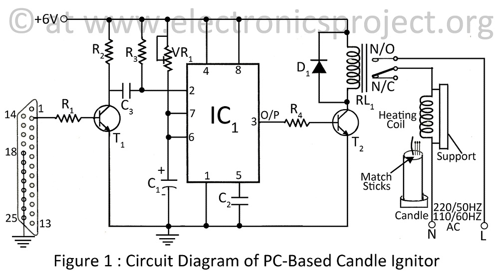
A PC-based candle ignitor is a verified project designed for computer students, utilizing a 555 timer circuit to ignite a candle. The project includes a computer circuit diagram and software code written in C. The PC-based candle ignitor project integrates...

This figure illustrates a block diagram of modern automated systems that incorporate closed-loop feedback for motion control. These systems typically feature a servo system consisting of feedback elements and a motor driver, which work together to provide accurate and...
This is an FM transmitter circuit that utilizes logic gates. The circuit features a radio frequency (RF) oscillator, which operates with a 10.7 MHz ceramic filter. The FM transmitter circuit is designed to modulate audio signals onto a carrier frequency...
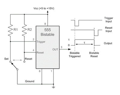
By applying a "LOW" signal to the Trigger input (pin 2) while the switch is in the Set position, the output state changes to "HIGH". Conversely, applying a "LOW" signal to the Reset input (pin 4) while the switch...
A radio remote control system utilizing DTMF (Dual-Tone Multi-Frequency) technology is presented. This circuit allows for the control of various electrical appliances through radio frequency signals. The described radio remote control system employs DTMF tones, which are generated by a...