
radio transmission to get the GPS data
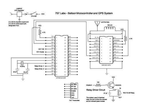
The schematic for the described system includes several key components. The microcontroller serves as the central unit, interfacing with the GPS module, the HX1 transmitter, and the camera. Power management is critical; thus, a battery pack capable of sustaining high current outputs at low temperatures is integrated. The 7805 voltage regulator is positioned to ensure stable voltage supply to the microcontroller and peripherals, with careful consideration of the minimum input voltage required for proper operation.
Relay drivers are implemented to control the camera shutter and buzzer, with the 2N2222A transistors providing necessary current buffering. The relays are rated for sufficient current handling, ensuring reliable operation under load. The APRS transmission system is connected to the microcontroller, allowing for periodic data updates regarding altitude and location.
The design also incorporates protection against environmental factors, such as RF interference, through the use of shielding. The parachute design is included in the overall system layout, ensuring a controlled descent and safe recovery of the payload. Each component is carefully chosen to withstand the extreme conditions expected during flight, and the entire system is designed to function cohesively, ensuring successful data collection and retrieval.The balloon went to 103, 258 ft peak reported altitude. Many items had to be considered for launching payload to this range. Unlike building an electronics package to operate at Sea Level, items such as air pressure, temperature, relative humidity and even shock events from the payload being tossed about by high altitude high velocity winds. The ap proximate air pressure at burst altitude was 0. 0218 psi with a projected temperature from NOAA Sounding data at -60 F. There was a colder band that the balloon had to travel through that was about 15, 000 ft thick with a temperature range at -84 F The original concept for the payload revolved around how to either receive or record data while in flight. The ideas ranged from the original of an Arduino with a SD Card shield to using FRS Radio to communicate the location.
After debate and gathering information, it was decided to work for an end design that comprised of a GPS module capable of reporting altitude through the entire possible flight range, some sort of radio transmission to get the GPS data to a ground station and a microcontroller to link the onboard camera and all other systems together. One of the primary concerns was being able to power all of the electronics and have the batteries last through the temperature extremes and the amount of power drain that was projected for the entire circuit.
There was no time to create a Spice model for the LDO Voltage Regulator used on the two circuit cards; however, a model is available for a standard 7805 +5V regulator. As shown in the following picture, one concern is how low the voltage could get on the battery pack before the regulator would cut off.
In the picture the left cursor is at approximately 6. 6 VDC. This is the point at which the input must remain above for the 7805 in order to obtain a stable 5. 0 volt output. This battery is capable of operating at temperatures down to -40 F with a constant current discharge rate over 1 Ampere for over 3 hours at a final voltage output of 1. 0 Volts. The idea was to be able to survive a high current drain and maintain a total power pack voltage level above the projected 6.
6 Volt value. This would ensure that we were able to provide a stable voltage source to all components. This was very vital in the case of the digital camera. The camera was drawing 0. 6 Amps at 3+ volts. The power for the camera was modified to run multiple twin cell packs in parallel to prolong the voltage level. The camera was tested to shut down with a low power fault when the pack read below 2. 7 volts. It should be noted that the Vivitar VivaCam camera actually raises the voltage internally to 5 Volts for use in various circuits.
This is one reason that the 2. 7 V was a critical point. It appears to be the cutoff level for the onboard Boost Converter. The primary signal involved the "Enable" line for the HX1 transmitter chip. The chip, in order to transmit data, had to be turned on. The chip was capable of being directly driven with a TTL output from the MCU. No interface electronics were required. Because of the availability of components, it was chosen to use micro relays vice an opto-isolator circuit. To buffer an initial current draw from the relay coil, 2N2222A transistors were used to switch supply voltage to the relay coils.
The relays were capable of 1. 5 Amperes of operating current through the signal output pole. In the schematic "Relay Driver" "-1" and "-2" are the control outputs from the MCU to the buffer circuit. In the case of Relay Driver -1, the signal made the circuit for the shutter switch on the camera. This was a simple short circuit on the switch for a duration of 0. 5 seconds. A variable timing switching circuit was used to find the "lowest" duration that the camera required in order to shutter properly.
The camera would trigger with a duration as low as 0. 25 seconds; however, it was decided to at least double this value to be on the safe side. Relay Driver -2 signal was used to activate a piezo electric buzzer upon startup of the system. A chirp sequence was used to allow the flight ground crew to verify that the system was working upon switching on the power switch located on the outside edge of the payload package. In addition, the buzzer was supposed to start sounding for 10 seconds on a 61 second interval after the balloon at descended below 2000 ft upon the return side of the flight.
The GPS altitude code could not be debugged at the time so it was launched with what turned out to be the wrong guess:( The choice of data transmission methods was quickly resolved to be APRS. As a guide on how to merge the GPS, MCU and the transmitter. the Trackuino Project was used as a ground level entry. The project code can be found at A transmission interval of 61 seconds was chosen to try and be out of sync with other possible transmitters and increase the chances of our data package getting through the system.
When payload was powered up, APRS transmissions were received for the entire flight. The data started to appear when the balloon exceeded 2000 feet and it showed up at On the return trip the last reported altitude was around 3000 feet to Internet via the APRS system. This was more than likely caused by the long transmission interval chosen and the radio horizon of the balloon to various receivers on the way up and down.
The main concern with pressure is what is going to happen to items in your payload Remember as pressure decreases the boiling point of fluids go down too! This very fact can lead to explosive decompression of parts like electrolytic capacitors. Try sticking one in a bell jar and pulling a vacuum on it:) Life can get real interesting quick. Remember any thing that has "gas" trapped in it will expand upon the reduction of external pressure on the container holding it.
It is all a matter of how well something is sealed that will allow it to survive or not. The only concern with the project revolved around capacitors and the power supply. The camera had a very large electrolytic capacitor for the flash circuit that could have ruptured but did not. The batteries were an unknown item. It was possible that something could break down with the Lithium batteries because it has a vent system built into it in the event that the unit overheats and starts to off gas.
Here again, nothing happened. Relative humidity would not be so much of a concern if it were not for the expected low temperatures. Any moisture picked up at lower altitudes could turn into ice crystals. Pure water does not conduct electricity, but any dust or other films on the surface of the electronics could now mix with any fluids and lower insulation resistance, be conductive pathways for high frequency RF and all sorts of other general havoc.
On the flip side, the extremely low humidity (to a point of nothing) can allow static electricity to build up and create possible discharges. This in turn could cause damage or create electrical noise for the electronics. Once the HX1 transmitter chip was installed and activated on the Microcontroller board, the code appeared to have "bugs" in it.
It turned out that RF was being induced on signal lines close to the HX1 and were causing noise problems with the MCU to the point that the software would not execute properly. Instead of going back and re-wiring the MCU board, the low tech route of Reynolds Wrap was used to create a Faraday Shield around the MCU section of the board and to totally isolate the HX1 chip as much as possible.
This low tech solution worked wonderful with our pictures as evidence. Found a Parachute Design on the Web for a 12 pound Payload and scaled it down for a 1 pound (anticipated) Payload Weight. Went out and bought the Brightest Colored, lightest weight Rip-Stop Nylon I could find; just happened to be on sale that day for half price.
Bought enough to make 4 Parachutes (in case I messed up the first one or two) with material left over. Most of the shroud lines were common Kite String, but a heaver one ran straight from the Payload attachment point, through the shroud attachment point, through the apex of the Parachute, and on up to attach directly to the Balloon.
When I designed it, I was told that the anticipated weight of the Payload (still being built) would be around 1 pound. The parachute I built would have limited the descent speed of a 1 pound payload to around 15 mph. Just a day or two before launch I was told it weighed 1. 1 pounds (close enough not to have to build a larger parachute). However, AFTER it was launched and we were driving around following it on APRS, I was told it probably weighed more like 1.
8 pounds; that would explain the 25 mph descent speed we saw on APRS. I used Balloon Track, which is a Public Domain program that can be downloaded from. (Thank you EOSS for making this available!) To chose a Launch Location, I entered data from (put in City, Sounding/GFS Model 3 Hour, select UTC Date/Time, Text Only, Captcha) for several Launch Sites, let BalTrack do its thing, then took the Track Plots and grafted the Direction & Distances on to maps of the area to see the Flight Path and approximately where it would land for each location. This allowed us to be sure we stayed away from Airports and didn`t land in the water. We waited until the absolute last day that we could launch, and were *VERY* lucky that wind was blowing South West that day; 98% of the time the prevailing winds in this area blow directly out to sea (complicating retrieval somewhat since none of us owns a boat.
) APRS works absolutely fantastic for this kind of thing! We were able to follow it from immediately after launch, to just before final touchdown. We could monitor direct reception from it in the car, but were out of range just a few miles from it; fortunately we could also get it on APRS Web Pages (like APRS. fi). After launch it went directly South just as predicted, so we drove South well in to North Carolina staying a little ahead of it.
However, it then started going MUCH further West than anticipated so we pulled over and adjusted our plans. Finally we called back to Home Base at 757 Labs and got suggestions from them; by this time it had landed and they said it was in some woods near a road.
So we put the last known coordinates in the car`s GPS and let it guide us. When we got to the area we could once again get direct reception from it and could get its exact coordinates. Ended up walking about 1/2 mile up a dirt road, and 1/4 mile in to the woods. Since GPS is inaccurate in the woods (trees block visibility of Satellites) we wandered all around the general area.
We thought we heard it beeping at one point, but it stopped before we could follow it. Finally, after two trips in to the woods, lots of scrapes & scratches, hundreds of bug bites, mud up to our knees and 45 minute later Geoff announced "GOT IT!" He stood there completely still like a hunting dog pointing at it, afraid to move lest he lose sight of it. Even though most trees were 50 to 100 feet tall, there it was about 25 feet up with the very bottom of the antenna about 20 feet up.
We searched around and finally after a few tries with braches that were too short, we found one long enough to snag the Payload String and yank it down. What a feeling; up until now the project was a big success, but standing there with sweat dripping off us on a hot, humid August day in North Carolina knowing we had retrieved it.
Wow, now the project was a total success! Back in the car (damn that Air Conditioning feels good!) we marveled at the pictures from the camera. "Let`s celebrate, it` Miller time!" The entire system was single point of failure. We had no redundancy anywhere; if (almost) any component failed the whole system failed, but everything was "just good enough" to work.
The Build Team has to convey the final weight of the Payload to whomever builds the Parachute BEFORE it is launched, not after it`s in the air and we are driving around chasing it. I had trouble holding the neck of the Balloon closed while folding it over, attaching the Payload String, putting tie-wraps on it, and wrapping it in Duct Tape all while wearing rubber gloves; so next time I recommend that a second person is standing by to help with that part of the process.
Put an extremely loud beeper on it. We were probably within a few hundred feet of it and could hardly hear it through the trees. Thick foliage changes the "sound" of the beeper so you don`t recognize it as the same sound you heard on the workbench (it sounds like a much lower frequency. ) Consider having a way for the Payload Container to vent excess heat at low altitudes; everything inside was almost too hot to touch after retrieval.
A simple Servo to slide a vent opening on the top when the internal temperature is too high should work. 🔗 External reference
Related Circuits
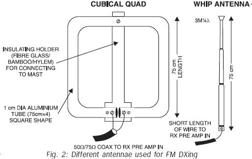
FM transmissions can be received within a range of 40 km. In fringe areas, the signal may be very weak. FM DXing refers to the practice of receiving distant stations (1500 km or more) on the FM band (88-108...

The CA3140 is a 4.5 MHz BiMOS operational amplifier featuring MOSFET inputs and a bipolar output. This operational amplifier integrates the benefits of PMOS transistors and high voltage performance. The CA3140 operational amplifier is designed to provide high-speed performance while...
The RF detector circuit, RF amplifier circuit, and automatic gain control circuit (AGC) are integrated within the IC, allowing for the straightforward construction of a high-quality and sensitive AM receiver using this IC. The ZN415E IC is an advanced...

The CMX866 is a multi-standard modem designed for use in telephone-based information and telemetry systems. Control of the device is achieved through AT commands via a simple 9600 b/s serial interface, which is compatible with various types of host...
Communication systems that utilize spread spectrum techniques are more resistant to noise, signal fading, and the Doppler effect compared to narrow-band systems. Through code division of signals (CDMA), frequency bands can be utilized more effectively, enhancing transmission privacy. Wide-band...
The design of a PAR 38 LED spotlight focuses on delivering practical LED lighting systems that meet performance expectations by reducing power consumption, extending lifespan, and enhancing overall efficiency. The PAR 38 LED spotlight is a widely used lighting solution...