
bidirectional dc motor driver schematic
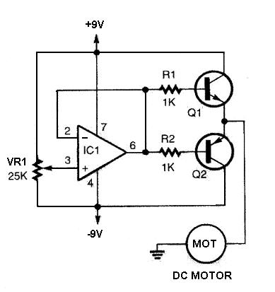
The DC motor driver circuit consists of a comparator that generates control signals for the power transistors. When the control voltage at pin 3 exceeds the voltage at pin 2, the output from the 741 op-amp goes high, forward biasing transistor Q1 and reverse biasing transistor Q2. Conversely, if the voltage at pin 3 is lower than that at pin 2, the output will drop, forward biasing transistor Q2 and reverse biasing transistor Q1. The transistors used in this application are TIP31 for Q1 (NPN) and TIP32 for Q2 (PNP). When Q1 is forward biased, it allows a positive current to flow through the motor, causing it to rotate clockwise. When Q2 is forward biased, the circuit provides a negative voltage source to the motor, allowing it to rotate counter-clockwise. The bias voltage applied to the bases of Q1 and Q2 influences the speed of the motor's rotation, with the adjustment provided by the variable resistor VR1 in the circuit.
The DC motor driver circuit demonstrates a practical application of op-amps in motor control systems. The 741 op-amp serves as an effective comparator, enabling precise control over the direction and speed of the motor. The use of TIP31 and TIP32 transistors allows for efficient switching and handling of the motor's current requirements. The design can be easily adapted to various applications requiring motor control, making it a versatile solution in electronic projects. Additionally, the circuit's simplicity facilitates understanding and implementation, making it suitable for both educational purposes and practical applications in robotics, automation, and other fields where motor control is essential.DC motor driver circuit in the following circuit images can be used for DC motor drivers and can control the direction of rotation in two directions with a DC motor rotation speed can be set. Under the DC motor driver circuit is quite simple and is built with a voltage comparator circuit 741 IC Op-Amp and a pair of NPN and PNP transistor driver.
D C motor driver circuit in the following figures can be worked on a symmetrical voltage source ± 9 volt and 6-9 volt DC motor load. DC motor circuits in detail can be seen in the following circuit images. Simple DC motor driver circuit above can control the direction of rotary speed control of DC motors and DC motor rotation.
Above DC motor driver consisting of the comparator and power a DC motor driver. Parts of comparator function is to provide control signals to the power transistor driver. At the time of the control voltage (pin 3) is higher than the voltage at pin 2 then the voltage comparator IC 741 IC 741 will provide the output voltage with a positive level, it will provide forward bias to reverse bias the transistor Q1 and the transistor Q2. then the voltage at pin 3 is lower than the voltage comparator IC pin 2 then gave the 741 will output a negative level, so that the transistor Q2 gets forward biased and reverse biased transistor Q1 gets.
The transistor is used as a DC motor driver is a type TIP31 transistors for Q1 and Q2 TIP32 for. At the forward bias of Q1 and Q2 have the reverse bias the DC motors have a positive current source through Q1 so that the DC motor to move in a clockwise direction. Then at Q2 and Q1 gets the forward bias to reverse bias DC motors have a negative voltage source to a DC motor to move counter-clockwise.
The size of the bias voltage on the base of Q1 and Q2 bidirectional DC motor driver circuit described above will affect the speed of rotation of DC motors. Bias voltage control transistor proficiency level by VR1 in circuit drver the bidirectional DC motor.
🔗 External reference
Related Circuits
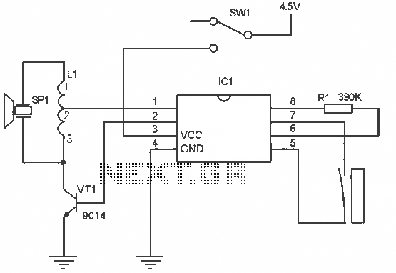
The alarm circuit operates as follows: When the power switch SW1 is turned on, the alarm system becomes active. If a magnet is brought close to the spring, the magnetic field attracts the spring, causing the dynamic and static...
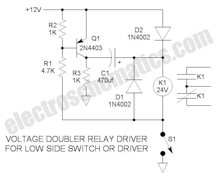
These novel relay driver circuits have the capability to activate a relay with a coil voltage rating that is double the supply voltage (Vcc). Once the relay is activated, the armature is maintained using Vcc, resulting in a significant...
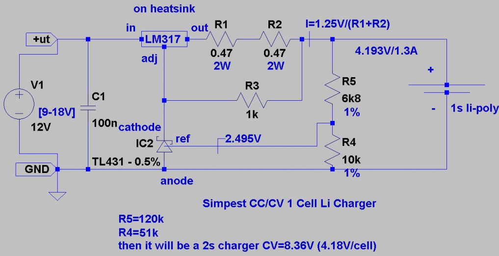
This is a Lithium-ion charger for LiPo batteries. The circuit schematic illustrates the configuration for charging a single 3.7V LiPo battery, but the voltage can be adjusted to charge multiple batteries in series. The LiPo charger establishes a current...
It is well known that pests like rats, mice, etc. are repelled by ultrasonic frequency in the range of 30 kHz to 50 kHz. Human beings can't hear these high-frequency sounds. Unfortunately, all pests do not react at the...
This is a schematic diagram of a stereo audio amplifier for a car. The circuit is powered by a single IC, the TDA1553, along with some external components. This IC is designed to manage the stereo car audio system....
This project involved designing an audio amplifier capable of delivering substantial output power with a minimal number of components while maintaining quality. The power amplifier section consists of three transistors and a few resistors and capacitors configured in a...