
Triangle Waveform Signal Generator

This circuit employs an operational amplifier (op-amp) configured in an integrator setup to produce a triangle waveform. The input signal is typically a square waveform, which the op-amp integrates to generate the desired triangular output. The frequency and amplitude of the triangle waveform depend on the characteristics of the input signal and the feedback components used in the circuit.
Key components of the circuit include resistors and capacitors that determine the time constants for charging and discharging, thus influencing the slope of the triangle waveform. The feedback resistor and capacitor values are critical; they must be selected carefully to achieve the desired frequency response and output amplitude. Additionally, the op-amp should be chosen based on its bandwidth and slew rate to ensure that it can handle the frequency of operation without distortion.
The circuit may also include diodes for clamping the output to prevent it from exceeding specified voltage levels, ensuring that the waveform remains within the desired range. Proper power supply decoupling is essential to maintain stability and reduce noise in the output signal. Overall, this configuration provides a reliable method for generating a symmetrical triangle waveform suitable for various applications in signal processing and waveform generation.A symmetrical, mV peak to peak triangle waveform can be generated by the circuit depicted in the following schematic diagram. This circuit is featured with.. 🔗 External reference
Related Circuits
The circuit has both square-wave and triangle-wave output. The left section is similar in function to a comparator circuit that uses positive feedback for hysteresis. The inverting input is biased at one-half the Vcc voltage by resistor R4 and...
This circuit is quite effective for testing or operating counters and stepping relays, as it eliminates the need for manually setting a switch for the desired number of pulses. By pressing the appropriate switches S1 to S9, one can...
The LH0024 is a small signal integrated circuit (IC) designed for general-purpose switching and amplification due to its low voltage characteristics. Additionally, it utilizes three 1N4148 silicon small signal diodes, which are planar epitaxial devices used for fast switching...

This is a series regulator with Q900 being the control element, Q901 a driver, and Q902 an error amp. ZD900 forms the emitter reference voltage source. Since the generated high voltage and other voltages are linked by means of...
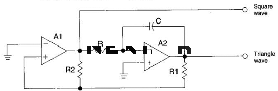
The circuit generates precision triangle and square waves. The output amplitude of the square wave is determined by the output swing of operational amplifier A1, while the ratio of resistors R1 to R2 sets the amplitude of the triangle...
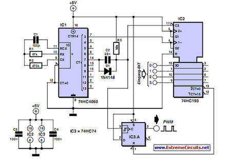
PWM waveforms are frequently utilized to regulate the speed of DC motors. The duty cycle of the digital waveform can be defined using an adjustable parameter. PWM (Pulse Width Modulation) is a technique employed to control the power delivered to...