
Railway Points Sequencer
This circuit design is particularly beneficial for model railway applications where multiple point switches are required to operate without overloading the power supply. The use of a sequencer ensures that the actuators are not subjected to high inrush currents that could lead to overheating and damage. The 555 timer, functioning as an astable multivibrator, generates a square wave signal that controls the timing of the sequencer, allowing for precise management of the switching sequence.
The 4017 Johnson counter, which has ten outputs, sequentially activates the triacs that control the power to each point actuator. This sequential activation prevents multiple actuators from being energized simultaneously, thereby reducing the risk of transformer overload and ensuring that the points operate smoothly. The adjustable potentiometer (P1) allows the user to fine-tune the switching interval based on the specific characteristics of the point actuators being used, which is crucial for optimizing performance.
The visual indication provided by the LED not only serves as a functional element but also enhances the user experience by allowing operators to monitor the status of the sequencer at a glance. The inclusion of a bridge rectifier and voltage regulator ensures that the circuit operates reliably within specified voltage limits, contributing to the overall robustness of the design.
In summary, this sequencer circuit is an effective solution for managing multiple point switches in model railway systems, allowing for efficient operation while safeguarding against potential damage to the actuators and power supply.Dedicated model rail enthusiasts using sophisticated train and points controllers often have the problem that as their layouts get bigger and more complex, the transformer supplying power to the points does not have enough current to switch several points at the same time. The actuators in the points are designed for ac operation so it doesn`t hel p by rectifying the supply and adding reservoir capacitors, the coils can overheat and burn out if they get jammed during their travel (ac operation actually helps to overcome friction in the mechanism). The circuit shown here solves this problem by using a sequencer to ensure than only one points actuator can be active at any point in time.
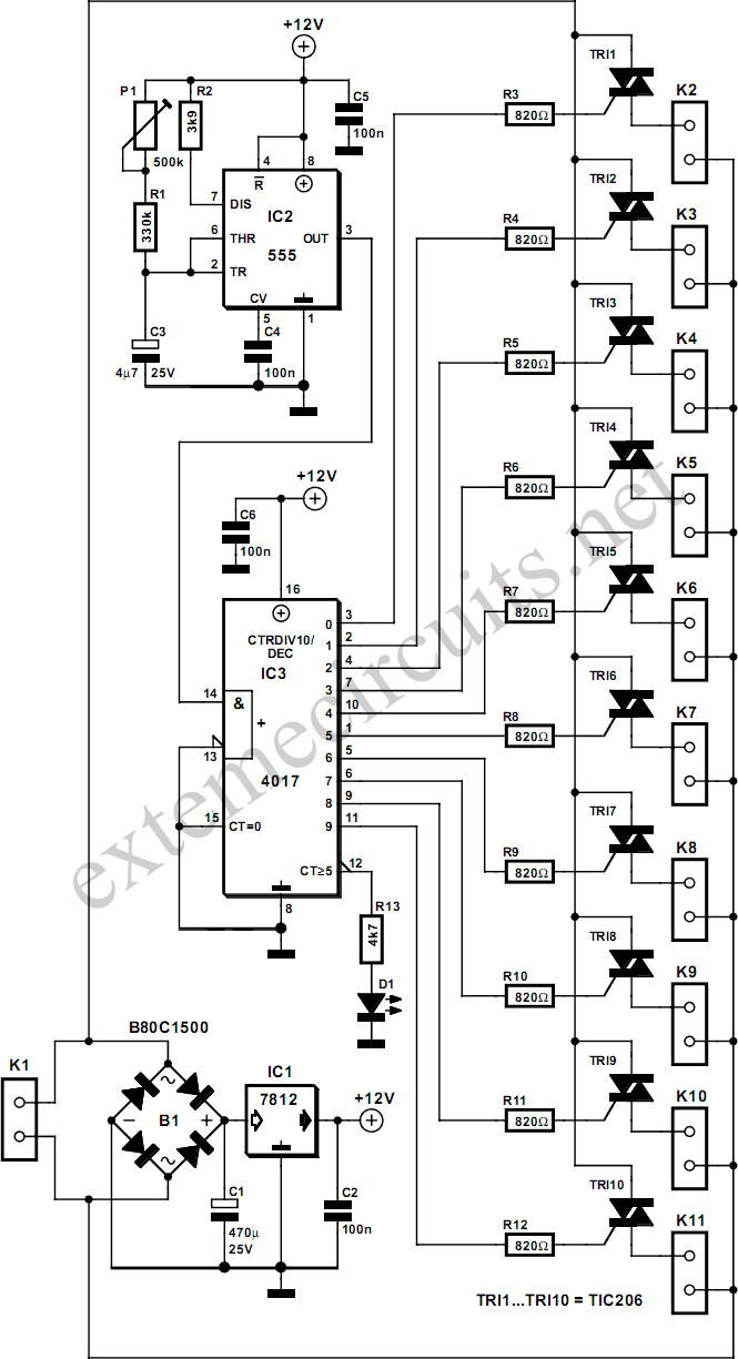
During operation the controller will switch all the points on one line at the same time as usual, but the other connection to each coil is connected to the sequencer unit. This circuit will only allow current to‚ow through one coil at a time. The sequencer circuit consists of a 555 timer congured as an astable multivibrator clocking a 4017 Johnson counter where the ten outputs are used to switch ten triacs in sequence, enough for ten sets of points.
P1 alters the oscillator frequency of the 555 timer and can be adjusted so that each time interval of the sequencer is long enough to allow the points to switch. The switching time varies depending on the type of points but is typically between 1 s and 1. 5 s. Any points that jam during switching give out a characteristic humming noise in time to the switching frequency so it makes them easier tond.
The eleventh output of the 4017 can be connected to an LED (together with a series resistor). This will flash to give a visual indication of the sequencers operation. Power for the circuit is provided by 15 V ac from the points transformer. The B80C1500 bridge rectifier (80 Vpiv, 1. 5 A) and regulator IC1 produce a stabilised 12 V for the circuit. Current consumption is only a few milliamps. 🔗 External reference
Related Circuits
Short circuits in the tracks, points, or wiring are almost inevitable when building or operating a model railway. Although transformers for model systems must be protected against short circuits by built-in bimetallic switches, the response time of such switches...
The circuit involves Clock and Load functions, with the Load function being described first. The component U5, a CD4013, is responsible for executing the load function by determining whether the shift register integrated circuits (ICs) operate in parallel or...
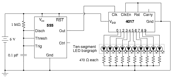
The following circuit illustrates a schematic diagram of an LED sequencer. This circuit is based on the 555 timer integrated circuit (IC). Features include a 555 timer circuit designed to debounce a mechanical switch, a 555 timer circuit to...
This circuit is similar to the LED clock using 12 neon indicator lamps instead of LEDs. It operates from 2 high capacity ni-cad cells (2.5 volts) which keep it going for a couple weeks. High voltage (70 volts) for...
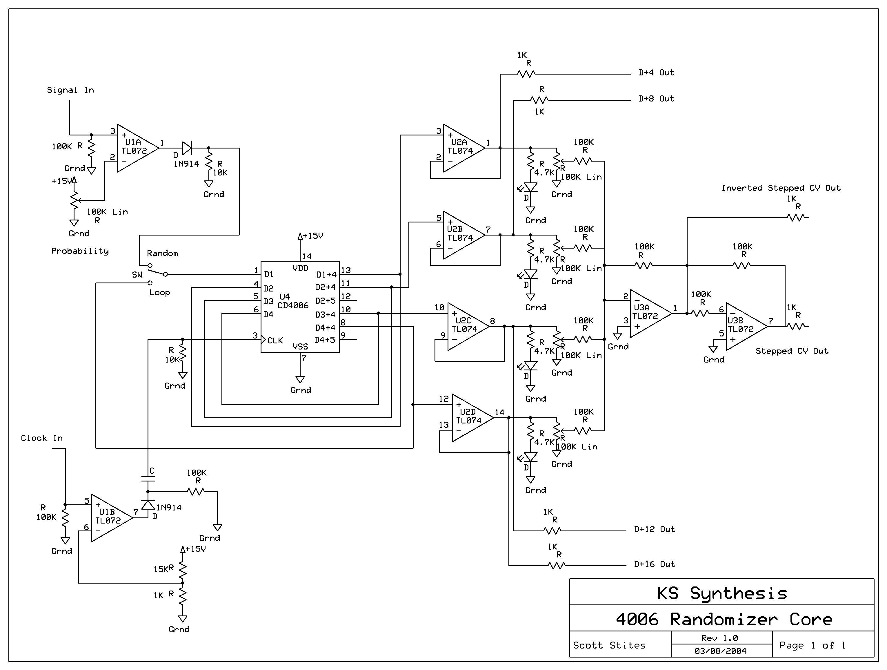
The mechanics of the Quantized Random Voltage function are intriguing. Instead of having fixed quantization steps for each output of the 4006 shift register, it is proposed to make the voltages adjustable through potentiometers. The Quantized Random Voltage function...
A sequencer used for music is a device that sequences musical events for predictable playback. For early electronic instruments, these sequencers often take the form of a collection of switches that are cued in series and which trigger some...