
Sound Alarm Circuit

The circuit operates by utilizing an electret microphone that converts acoustic signals into electrical signals. These signals are then fed into the LM386 audio amplifier, which is configured to boost the signal strength significantly. The gain of the amplifier is adjustable through the use of external components, specifically a capacitor connected between terminals 1 and 8, allowing for flexibility in the circuit’s responsiveness to sound levels.
The output from the LM386 is taken from pin 5 and sent to the Arduino, which processes this signal to determine if it exceeds the pre-defined threshold. The Arduino is programmed to monitor the analog input from the amplifier and trigger a digital output if the sound level surpasses a certain limit. This digital output is connected to an LED, which serves as a visual indicator of the alarm state.
In addition to the basic operation, the circuit design includes several capacitors that serve specific functions. For instance, C1 is critical for ensuring that only the AC component of the audio signal is passed to the amplifier, effectively filtering out any DC offset that could interfere with the detection of sound. Capacitors C2 and C3 enhance the amplifier's performance by stabilizing the gain and preventing unwanted oscillations, which could lead to false alarms or distorted sound output.
The arrangement of components and the careful selection of values for resistors and capacitors are essential for optimizing the sensitivity and reliability of the sound detection circuit. The design can be further refined by adjusting the gain settings or incorporating additional filtering stages if necessary, depending on the specific application requirements. Overall, this sound alarm circuit provides an effective solution for monitoring audio activity in designated quiet areas, ensuring timely alerts for any unauthorized sound events.This is a circuit that will go off if the circuit detects any sound above a certain threshold. Once the circuit detects sound, the alarm goes off alerting us to this sound. This circuit has extreme use when an area ordinarily should be very quiet and should have no sound like a quiet zone. Under quiet conditions, with little to no sound, the alarm will not go off. When a sound is detected such as someone walking through the room or talking in a room, the alarm will go off. Thus, we can detect intruders in a room that shouldn`t be there if they create sound while operating in a room where there shouldn`t be any.
So in order to build our circuit, we will use a microphone and connect it to an audio amplifier to get amplified signals. The amplifier IC that we use is the popular LM386 IC. This IC will amplify the output signals that the microphone produces so that the arduino will be able to detect large enough signals to interpret them.
All we need to do then is connect the 3 terminals on the board, which are VCC, GND, and AUD. Vcc is the power which we supply to the breakout board, so that the microphone and amplifier have sufficient power to operate. GND is the negative or return path of the power. And AUD is the output of the microphone board, which are the amplified sound signals. Using this board greatly simplifies the process of building our sound alarm circuit, since we don`t have to put the electret microphone and amplifier together.
However, if you do want to do so, do so. Again, click the above link to the circuit schematic. Before we show the complete schematic diagram of the arduino sound alarm circuit, we will first show the pinout of the LM386. This way, the connections that we make from the microphone to it will make more sense. Terminals 1 and 8 represent the gain control of the amplifier. These are the terminals where you can adjust the gain by placing a resistor and capacitor or just capacitor between these terminals.
In this circuit, we will place a 10G‚ µF capacitor between these terminals for the highest voltage gain. You can adjust this as necessary to adjust the gain, as needed. Terminals 2 and 3 are the sound input signal terminals. These are the terminals where you place the sound which you want to amplify. In our case for this circuit, the elecret microphone will be connected to these terminals. Terminal 2 is the -input and Terminal 3 is the +input. In our circuit, the positive microphone terminal will be placed on terminal 3 and terminal 2 will be connected to the negative microphone terminal, tied to ground.
Terminal 7 is the Bypass terminal. This pin is usually left open or is wired to ground. However, for better stability, a capacitor is added in our circuit because this can prevent oscillations in the amp chip. R1 is a resistor that connects the microphone to positive voltage so that the microphone is able to power on.
Microphones cannot work without the necessary power needed. C1 is a capacitor that blocks DC voltage on the input signal and allows AC to pass through. When we speak into a microphone, our voice or music is the AC signal. This is the only part of the signal that we want to pass through to output. The DC signal is only used to give power to the microphone; we do not want it to appear in output. This is why we use this capacitor. It blocks the DC but allows the AC to go into output. C2 is a capacitor that sets the voltage gain of the LM386 amplifier. Therefore, the voltage out is 200 times the voltage in. This provides us with the maximum gain that the LM386 can provide. C3 is a capacitor that improves the stability of the LM386 amplifier to prevent issues such as oscillations. Oscillation can distort sound signals, making them unclear or unintelligible. C5 is a capacitor that acts as a current bank for output. This capacitor drains when sudden surges of current occur and refills with electrons when the demand for current is low.
The circuit starts with the electret microphone. The microphone picks up sound signals and transforms them into electrical signals. These electrical signals are then amplified by the LM386 IC. These signals are then output through pin 5 of the amplifier IC, which are then fed to the arduino board to be processed. The output signal, again, comes from pin 5 of the LM386 IC. The positive terminal (+) goes into an analog terminal of the Arduino; we will connect it, in our case, to A0 of the analog terminal.
The negative terminal (-) connects to GND on the arduino. This allows us to process the output signal of the microphone. If we don`t speak into the microphone, it will pick up a faint signal and give us a very low reading. If we make loud noises such as shout, clap into the microphone, etc. , we will get a loud reading. We will program the software for the arduino to light up the LED attached to digital pin, D13, when a certain threshold of sound is reached.
The LED will light up and stay on unless power to the circuit is shut off. This way, our circuit functions as a sound alarm circuit. 🔗 External reference
Related Circuits
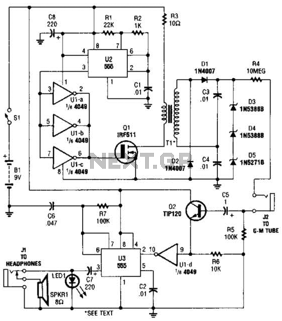
The circuit is constructed using a 4049 hex inverter (U1), two 555 oscillator/timers (U2 and U3), two transistors, a Geiger-Muller tube, and several additional support components. The first 555 timer (U2) is set up for astable operation. The output...
This AC motor speed controller can handle most universal type (brushed) AC motors and other loads up to about 250W. It works in much the same way as a light dimmer circuit; by chopping part of the AC waveform...
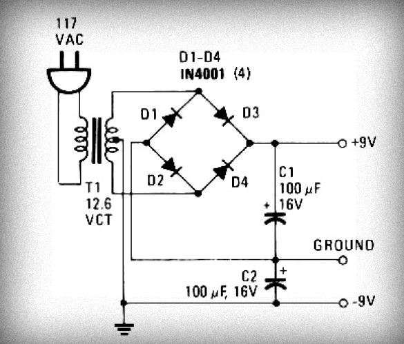
Initially, voltage from AC 220V or 110V enters the transformer, which reduces it to 12V AC. This AC voltage is then rectified using either four diodes or a bridge rectifier to convert it to DC voltage. The resulting DC...
The Pulse Demodulator, as illustrated in the accompanying image, consists of a CMOS Hex Inverter. This circuit is capable of performing envelope detection on amplitude pulses. The Pulse Demodulator utilizing a CMOS Hex Inverter is designed to extract the envelope...
This circuit operates at potentially lethal 220V AC mains voltage. The circuit should be built and used only by individuals who know how to safely work with such dangerous voltages and how to construct the circuit to ensure safety....

Introduction to the circuit schematic depicted in Figure 3-3. In this configuration, the 555 timer is utilized in a monostable mode, typically activated by a normally open push button switch. The circuit operates in an S-shaped state, where the...