
Warble Alarm Circuit
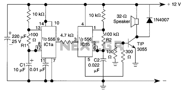
The circuit employs a dual timer configuration, leveraging the capabilities of the 556 timer, which contains two 555 timer circuits in a single package. The first timer is configured in astable mode, generating a continuous square wave output. The frequency of this output is primarily influenced by the resistors R1 and R2, as well as the capacitors C1 and C2. The relationship governing the frequency of oscillation can be described by the formula:
f = 1.44 / ((R1 + 2*R2) * C1)
where f represents the frequency in Hertz, R1 and R2 are the resistances in ohms, and C1 is the capacitance in farads.
The output from the first timer is then fed into the second timer, which is configured to modulate the square wave signal. This modulation results in the generation of two distinct frequencies, approximately 400 Hz and 500 Hz, which alternate to create a warbling effect. This is achieved by adjusting the values of R1, C1, R2, and C2, allowing for precise control over the output frequencies.
The circuit is typically powered by a DC voltage supply, which must be within the operating range of the 556 timer IC. To ensure reliability and stability, decoupling capacitors may be added to the power supply lines. Additionally, the output signal can be connected to a speaker or buzzer, which converts the electrical signals into audible sound, effectively producing the desired alarm tone.
Overall, the design is compact and can be implemented in various applications requiring an audible alarm, making it suitable for integration into emergency vehicle systems or other alert mechanisms. Proper selection of component values is critical for achieving the intended sound characteristics and ensuring optimal performance of the circuit. This circuit uses a 556 to first generate a low frequency square wave, that is modulated to produce two alternate tones of about 400 and 500 Hz. Circuit generates warble alarm of European emergency vehicles. The frequencies of the oscillators are determined by the values of Rl, CI and R2, C2. 🔗 External reference
Related Circuits

This type of charger transfers RF energy from an inductor (L2) to an external pickup coil. The pickup coil is connected to a rectifier and a battery that requires charging. This design is advantageous as it eliminates the need...
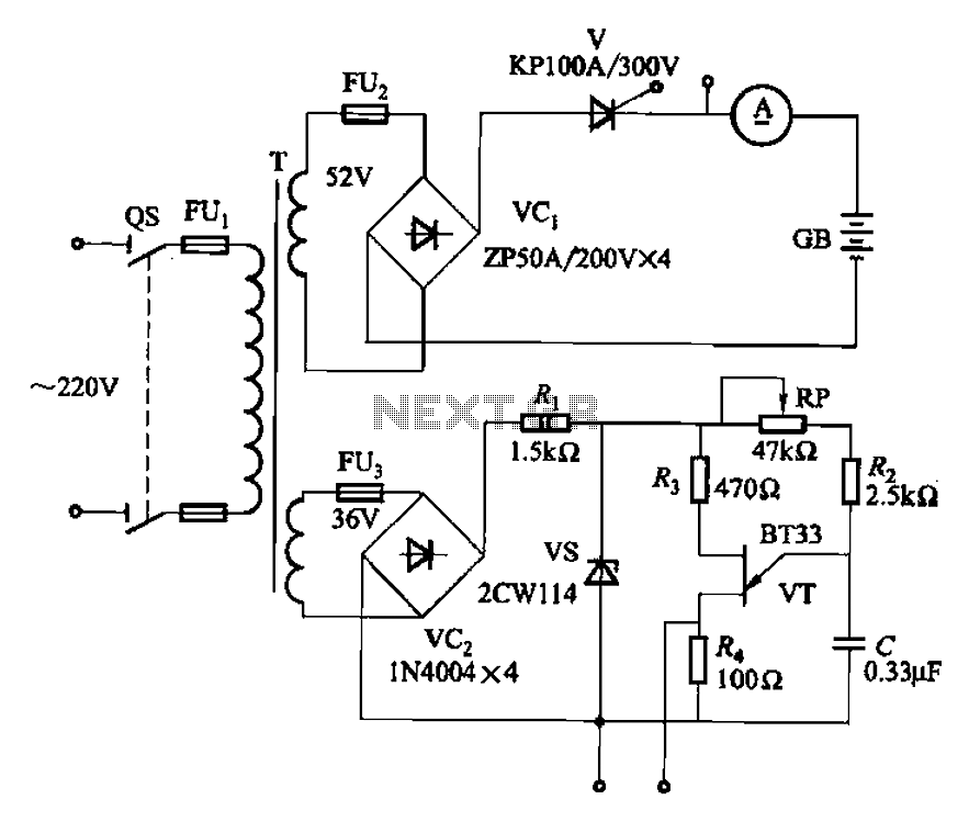
The adjustment potentiometer RP can modify the magnitude of the DC output voltage. The adjustment potentiometer, designated as RP, is an essential component in various electronic circuits, particularly in power supply systems and signal conditioning applications. It serves as a...

This circuit generates a siren sound when switch S1 is pressed. The sound frequency increases as capacitor C1 charges, and when switch S1 is released, the frequency decreases as capacitor C1 discharges. The circuit operates on a simple principle of...
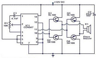
The circuit operates on the principle that insects, such as mosquitoes, can be repelled using sound frequencies in the ultrasonic range (above 20 kHz). It utilizes a Phase-Locked Loop (PLL) integrated circuit, specifically the CMOS 4047, configured as an...
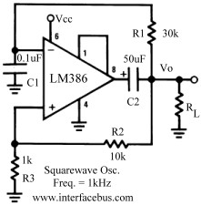
Several operational amplifier circuits are presented here, configured as square wave oscillators. A square wave is a periodic pulse train with a 50 percent duty cycle. The operational amplifier functions as a high-gain amplifier, and oscillation is achieved with...
This circuit is designed to drive a relay coil using a low power output, typically from an integrated circuit (IC) such as a 555 timer or a TTL/CMOS device. It facilitates the switching of high loads or loads requiring...