
radio receiver circuit long and medium wave
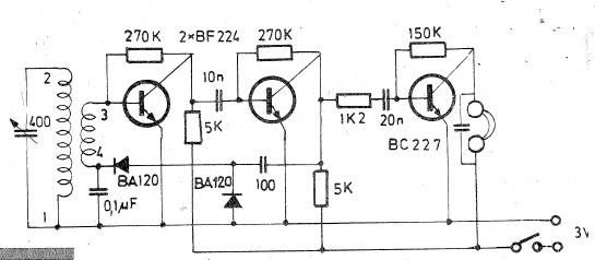
The described oscillating circuit utilizes a ferrite bar as the core material, which enhances the inductance of the coils and improves the circuit's efficiency in receiving radio waves. The choice of 135 turns for winding "1-2" in the long wave configuration and 75 turns in the medium wave configuration indicates a design optimized for different frequency ranges. The number of turns directly affects the inductance and resonant frequency of the circuit, which is crucial for effective signal reception.
The use of CuEm wire with a diameter of 0.15 mm is significant as it provides the necessary conductivity while maintaining a manageable physical size for the windings. The wire's resistance and skin effect at radio frequencies must be considered, ensuring the circuit operates effectively across the intended frequency bands.
Incorporating a variable capacitor of 40-400 pF in parallel with winding "1-2" allows for fine-tuning the resonant frequency of the circuit. This adjustability is essential for optimizing reception and selecting specific stations within the long or medium wave bands. The variable capacitor should be carefully selected to ensure it can handle the voltage and current levels present in the circuit.
The high-impedance headphones rated at 1000-2000 ohms are suitable for this application, as they are designed to work with low-power audio signals generated by the oscillating circuit. The inclusion of a 10 nF capacitor in parallel with the headphones serves to filter out any high-frequency noise and improve the overall sound quality, allowing for clearer audio reception.
Overall, this oscillating circuit design is a practical approach for listening to long and medium wave radio frequencies, combining specific coil configurations, a variable capacitor, and high-impedance headphones to achieve effective signal reception.Oscillating circuit (coil) are made on a ferrite bar. If you wish to listen long waves winding "1-2" has 135 turns and 3-4 has 20 turns. If you wish to receive medium wave winding "1-2" has 75 turns, and "3-4" has 7 turns (wire used must be CuEm 0. 15mm). In parallel with the winding 1-2 is necessary to connect a 40-400pF variable capacitor. Listen ing signal is made using high impedance headphones to 1000-2000 ohms, which have a capacitor of 10nF in parallel. 🔗 External reference
Related Circuits
A potentiometer regulates the firing point of the triac. Capacitor C4 is charged through resistors R3, R4, P1, and R5. After a specific duration, determined by the potentiometer setting, the charge in C4 becomes sufficient for the diac D...

This is an AC-powered LED flasher that can drive two high-bright LEDs directly from the power obtained from the AC lines. The high-bright LED flasher can be... The AC-powered LED flasher circuit is designed to illuminate two high-bright LEDs using...
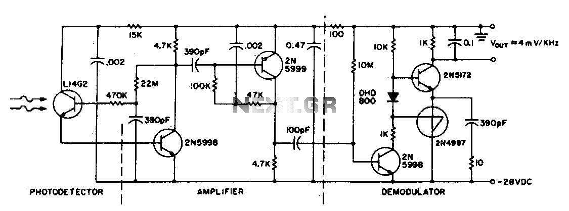
This circuit consists of an L14G2 detector, two stages of gain, and an FM demodulator. Better sensitivity can be obtained using more stages of stabilized gain with automatic gain control (AGC). The circuit design features an L14G2 detector, which serves...
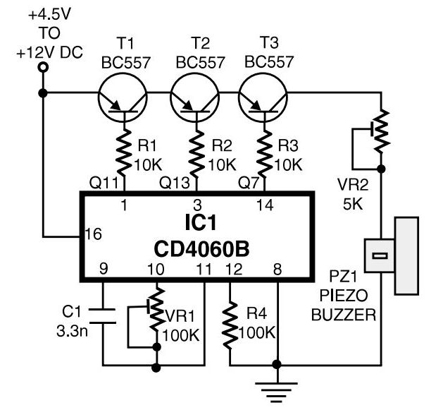
This is a simple home telephone ringtone generator circuit built using only a few electronic components. It generates a simulated telephone ringtone and requires a DC supply of 4.5V to 12V. This circuit can be used in ordinary intercom...
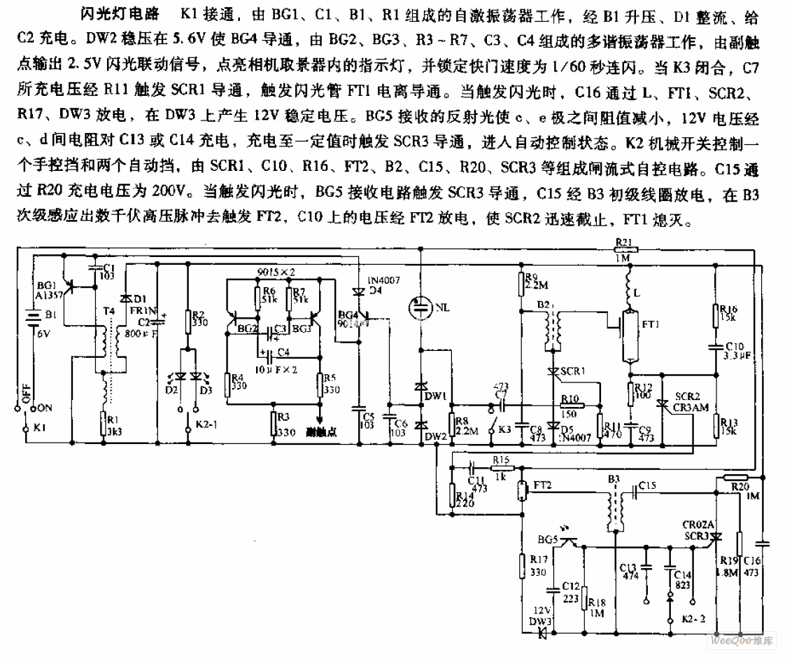
The camera flashlight circuit activates when switch K1 is engaged. This triggers a self-oscillating circuit consisting of BG1, capacitor C1, battery B1, and resistor R1. Once operational, the circuit boosts the voltage through B1 and rectifies it using diode...

This jam circuit is designed for quiz contests, allowing participants to press their button (switch) to gain the first opportunity to answer a question. The circuit accommodates up to eight contestants, each assigned a unique number (1 to 8)....