
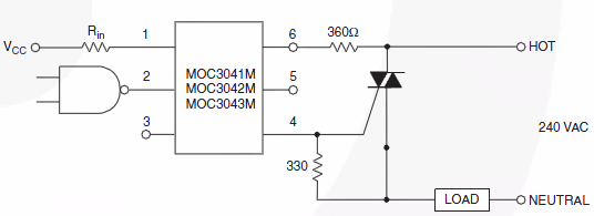
equivalent circuit of a solid state relay
To implement a switching circuit for 50V AC voltage with a maximum current of 5A and a frequency of 50Hz using MOSFETs or alternative transistors, the following considerations are essential. The circuit design must accommodate the voltage and current specifications while ensuring safe operation and reliability.
A suitable MOSFET should be selected based on its voltage rating, current handling capability, and switching characteristics. The chosen device must have a drain-source voltage (V_DS) rating higher than 50V to provide a safety margin. Additionally, the continuous drain current (I_D) rating should exceed 5A to ensure the transistor can handle the maximum load without overheating.
The circuit will require a proper gate drive configuration to ensure that the MOSFET operates efficiently. A gate resistor may be included to limit the inrush current to the gate capacitance during switching, which helps prevent voltage spikes that could damage the MOSFET. A pull-down resistor can also be added to ensure that the gate is pulled to ground when not driven, preventing accidental turn-on due to noise.
For AC switching, the MOSFET should be configured in a way that allows it to handle the AC waveform effectively. A common approach is to use a full-bridge configuration with four MOSFETs, allowing for control of both halves of the AC cycle. Alternatively, a single MOSFET can be used in conjunction with a transformer or relay to switch the AC load, but this may complicate the design.
Thermal management is another critical aspect of the design. Adequate heat sinking should be provided to dissipate heat generated during operation, especially since the switching speed is not a concern, leading to longer conduction times and increased thermal stress on the device.
In summary, the circuit design should focus on selecting appropriate MOSFETs or alternative transistors, ensuring proper gate drive circuitry, managing thermal dissipation, and configuring the circuit to effectively switch the 50V AC load at the specified current and frequency. This approach will provide a cost-effective solution while maintaining functionality and reliability.Switch 50V AC voltage. Maximum drained current will be 5A. Frequency is 50Hz. Switching speed is not important, can be real slow, it is not a problem in my application. I wanted to use solid state relay at first for this purpose. But as soon as I started to search an SSR, I saw that their prices are too high. For a cheaper alternative solution, I want to use MOSFET transistors (can be a different transistor type as well) instead of solid state relay. 🔗 External reference
Related Circuits
The circuit comprises an N-MOSFET voltage follower (T1, common drain) and a current source (T2, NPN Darlington). The current source is set to 2.2 Amps. With a supply voltage of 40V, the circuit can deliver approximately 17W into an...
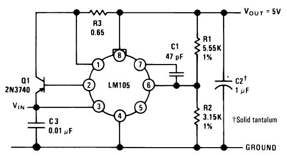
A single diffused, wide base transistor, such as the 2N3740, is recommended due to its reduced tendency to cause oscillation issues compared to double diffused, planar devices. Additionally, it exhibits greater reliability under overload conditions, and low-cost options are...
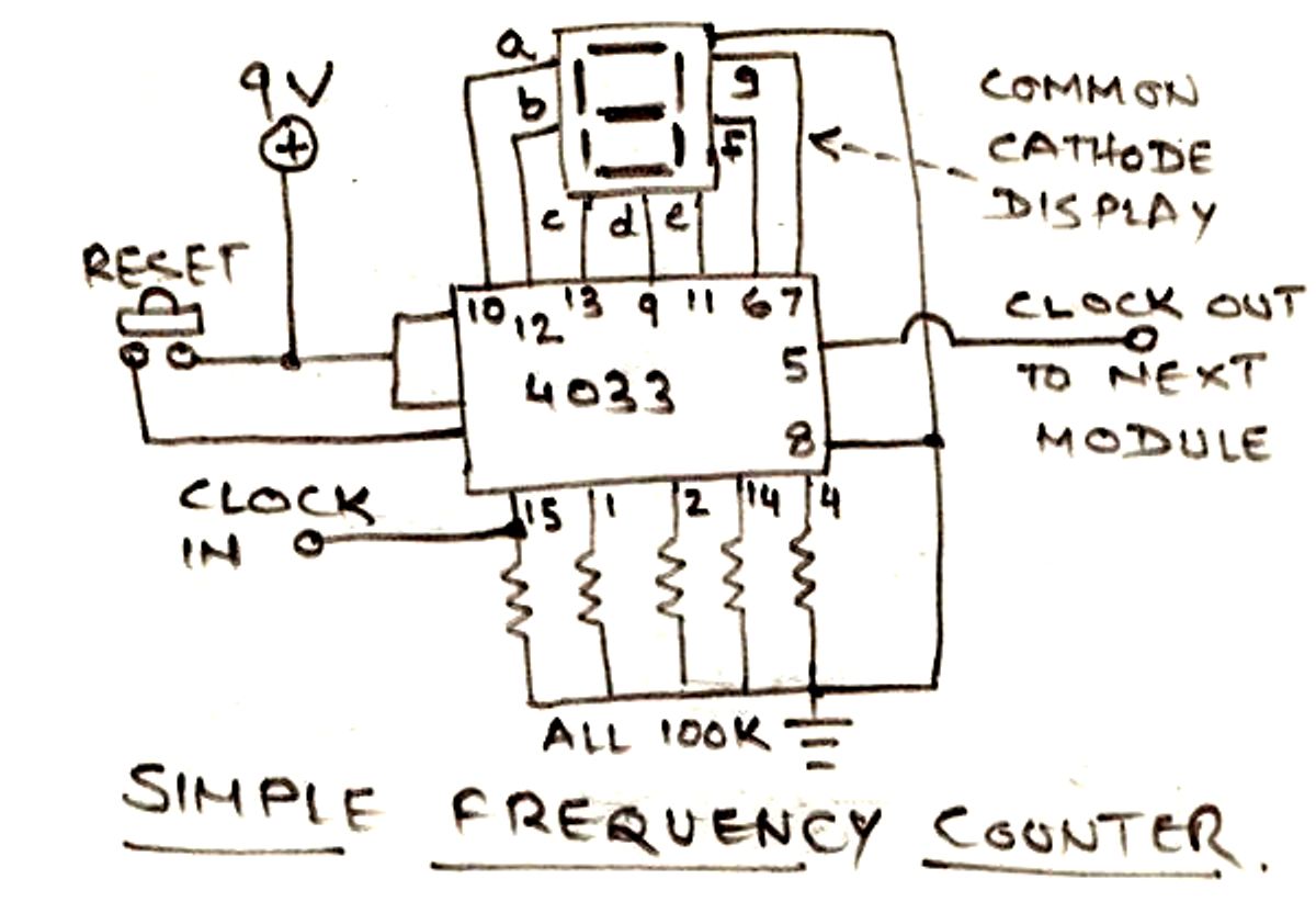
The circuit illustrated below is designed for measuring frequency in Hertz (Hz). It is straightforward to construct, utilizing a single IC 4033 and a common cathode display as the main components. For measuring higher frequencies, typically in the range...
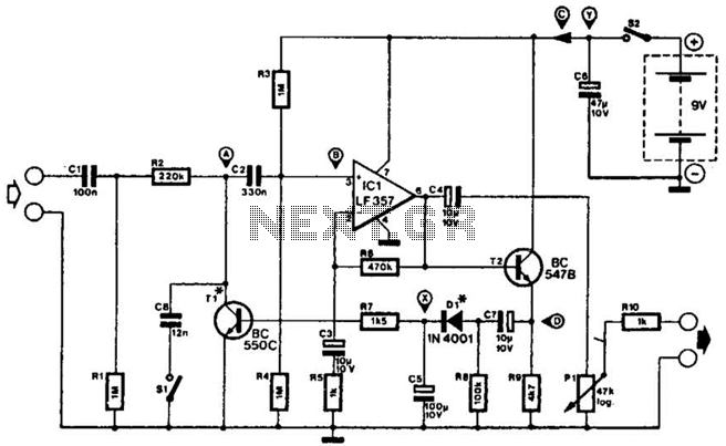
This compressor will compress a 25-mV peak-to-peak (p-p) audio signal to a 20-V p-p output, maintaining input levels between 1.5 V p-p and 3.5 V p-p, with a frequency response ranging from 7 Hz to 67 kHz. It is...
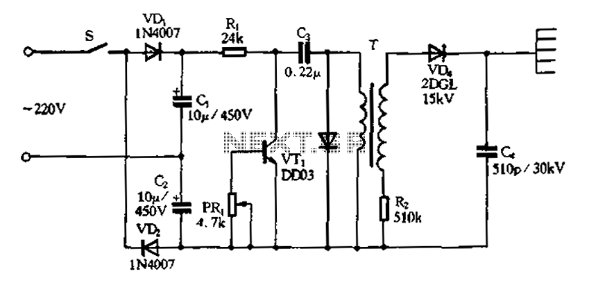
Doubling rectifier circuit in a negative ion generator application circuit. The doubling rectifier circuit is an essential component in negative ion generator applications, where it plays a crucial role in converting alternating current (AC) to direct current (DC) while also...
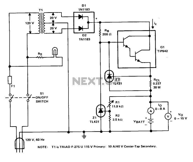
The charger operates with a charging voltage of 2.4 V per cell, aligning with the recommendations of most manufacturers. The circuit delivers a charging voltage of 14.4 V (6 cells at 2.4 V per cell) in a pulsed manner...