Rangkaian Thermometer Berbasis Mikrokontroler AT89S52
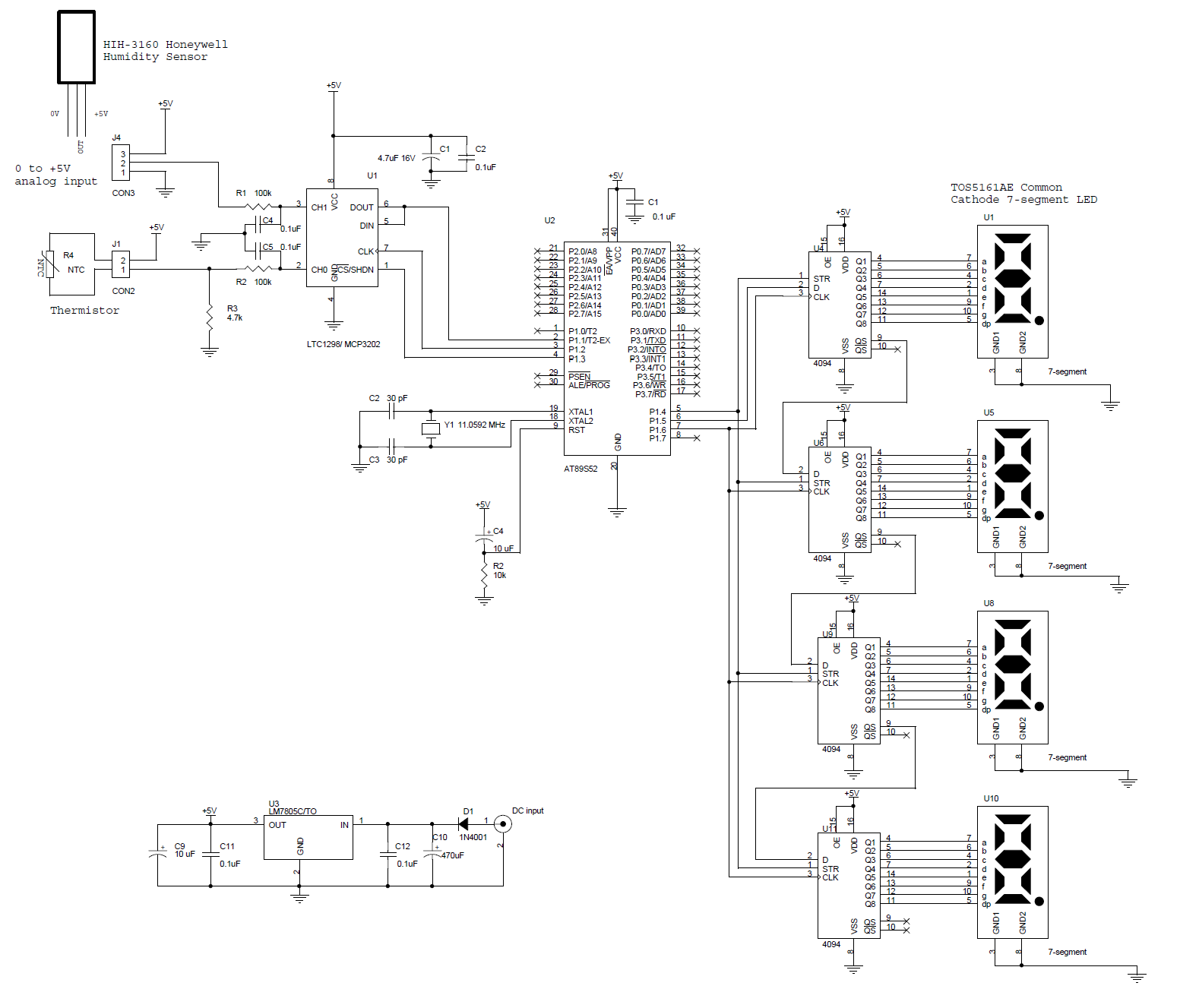
This circuit features a microcontroller AT89S52 paired with a 12-bit ADC LTC1298. The programs are written in C and include digital filtering, interfacing with a 0.5-inch 7-segment LED display. The thermometer provides a sensitivity of 0.1°C. The hardware block and circuit diagram are illustrated below. The temperature sensor used is an epoxy-molded thermistor, and the signal conditioning is achieved through a simple voltage divider. The ADC, which operates via a 12-bit SPI interface, can be either the LTC1298 or the MC3202, featuring two channels: CH0 and CH1. The input signal from the thermistor is connected to ADC channel 0 through a voltage divider, while channel 1 is reserved for an additional sensor, exemplified by the HIH-3160 Honeywell Relative Humidity Sensor. The ADC is interfaced with the AT89S52 microcontroller using pins P1.1, P1.2, and P1.3. The 4-digit LED display is driven directly by a 4094 CMOS shift register.
The circuit operates as a digital thermometer utilizing the AT89S52 microcontroller, which is a popular 8-bit microcontroller from Atmel. The microcontroller interfaces with a 12-bit analog-to-digital converter (ADC), specifically the LTC1298, which communicates through a Serial Peripheral Interface (SPI). This ADC is capable of converting the analog voltage output from the thermistor into a digital value with a resolution of 12 bits, allowing for precise temperature readings with a sensitivity of 0.1°C.
The thermistor, an epoxy-molded type, serves as the temperature sensor. It is connected to the ADC through a voltage divider circuit, which conditions the signal to be compatible with the ADC’s input range. The ADC channels are configured such that channel 0 receives the thermistor input, while channel 1 is available for additional sensors, such as the HIH-3160 relative humidity sensor, which can be integrated for comprehensive environmental monitoring.
The microcontroller processes the digital data received from the ADC and implements digital filtering algorithms to enhance the accuracy of the readings. The processed temperature data is then sent to a 4-digit 7-segment LED display, which visually presents the temperature readings. The display is driven by a 4094 CMOS shift register, allowing for efficient control of the segment outputs while minimizing the number of microcontroller pins required for interfacing.
Overall, this circuit design effectively combines microcontroller technology, analog signal processing, and digital display to create a reliable and accurate thermometer suitable for various applications.This is a circuit of a microcontroller AT89S52 Thermometer and 12-bit ADC LTC1298, programs written in the language c program with digital filtering and interface the LED display. The reading provides 0. 1C sensitivity. The hardware block and circuit diagram is shown in Fig below. The sensor is epoxy molded thermistor. The circuit for signal condit ioning is a simple voltage divider. The ADC is 12-bit SPI interface LTC1298 analog-to-digital converter. The microcontroller is Atmel 89S52. The display has four digits 0. 5 inches 7-segment LED. The segment driver provides 32-bit CMOS output. The ADC is 12-bit (LTC1298 or MC3202) are two channels, CH0 and CH1. The input signal from thermistor for ADC channel 0 is simple voltage divider. Channel1 is available for other sensor. The sample shown in schematic is HIH-3160 Honeywell Relative Humidity Sensor. The ADC chip is interfaced with MCU, 89S52 with P1. 1, P1. 2 and P1. 3. The display has 4-digit LED. The 4094 CMOS shift register drives the LED directly. 🔗 External reference
